It’s not a stretch to say that most devices these days have settled on USB as their power source of choice. While we imagine you’ll still be running into the occasional wall wart and barrel jack for the foreseeable future, at least we’re getting closer to a unified charging and power delivery technology. But are all USB chargers and cables created equal?
The answer, of course, is no. But the anecdotal information we all have about dud USB gear is just that, which is why [Igor Brkić] wanted to take a more scientific approach. Inspired by the lighting bolt icon the Raspberry Pi will flash on screen when the voltage drops too low, he set out to make a proper examination of various USB chargers and cables to see which ones aren’t carrying their weight.
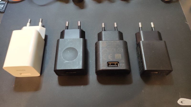
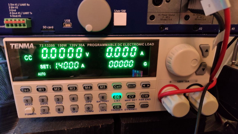 In the first half of his investigation, [Igor] tests four fairly typical USB chargers with his TENMA 72-13200 electronic load. Two of them were name brand, and the other just cheap clones. He was surprised to find that all of the power supplies not only met their rated specifications, but in most cases, over-performed by a fair amount. For example the Lenovo branded charger that was rated for only 1 A was still putting out a solid 5 V at 1.7 A. Of course there’s no telling what would happen if you ran them that high for hours or days at a time, but it does speak to their short-term burst capability at least.
He then moved onto the USB cables, were things started to fall apart. The three generic cables saw significant voltage drops even at currents as low as 0.1 A, though the name brand cable with 20 AWG power wires did fare a bit better. But by .5 A they were all significantly below 5 V, and at 1 A, forget about it. Pulling anything more than that through these cables is a non-starter, and in general, you’ll need to put at least 5.2 V in if you want to actually run a USB device on the other side.
Admittedly this might not be groundbreaking research, but we appreciate [Igor] taking a scientific approach and tabulating all the information. If you’re still getting low voltage warnings on the Pi after swapping out your cheapo cables, then maybe the problem is actually elsewhere.


I would love a little test box, like a battery tester, that told me which usb power supplies and cables were good and which were crap, since I have so many floating around I could toss the crappy ones if I knew they were objectively crap.
+1
Check Amazon or other sites for “USB Load Tester,” you’ll find several adjustable load/DVM combos to test chargers and cables. They are mostly around $20, not expensive at all. I got one a couple weeks ago and learned a lot about my chargers and cables. The one I got has an auxiliary board that plugs in and lets you select higher voltages on chargers that support more than 5V.
Thanks. Here I come Bezos!
That could be as simple as a currentsource with a USB A or C socket and a bunch of USB B, micro, nano, etc sockets where the 5V and ground are shorted.
Then the output voltage of the current source is the voltage drop for a given current.
A short-circuit is not going to provide you much in the way of testing your power supplies, outside the short-circuit shutdown function. You need a controlled load, whether it be a simple resistor (mildly useful) or a programmable DC load (allows you to find out just how much power you can draw before things get bad). A simple 5-Oh, 7.5-or-higher-Watt resistor would allow you to test with a 1 Amp load.
Yes, I have had that issue too. So I scratched that itch, with this project: https://forum.swmakers.org/viewtopic.php?f=9&t=2452 In it’s current form, it can test USB Micro and iPhone cables, and put up to a 1.5A load onto a battery bank.
Looks cool, you should do a writeup of HaD.
Tindie has one for a few dollard. They work nice.
Anyone that that design stuff relies on tighly regulated 5V from USB obviously haven’t read the spec or even the wiki.
The spec allows for a very wide range to accomodate for cable/connector/ PTC fuse/protection circuit drop on top of load regulation.
5.00 +0.25 −0.60 V
5.00 +0.25 −0.55 V (USB 3.0)
The Pi low voltage warning triggers around 4.65v, which isn’t unreasonable. It’s nuts that it’s so difficult to even get *that* out of most usb power supplies/cables. A whole bunch of problems went away when I started using 5.2V supplies instead, including for completely non-pi related stuff.
The Raspberry Pi boards really ought to have a buck/boost regulator to help overcome the inevitable voltage drop in the power cord from the wall-wart.
A Pi 3B+ draws up to 400 mA itself and will pass through up to 1.2 A to peripherals. Pulling 1.6 A from a wall-wart with nominal 5.0 V output permits a total only 0.22 Ohms of resistance in the connecting cord wires and any intervening connectors between the wall-wart and the Pi’s circuit board to maintain a 4.65 Volt input at the Pi.
I have noticed some of the official Raspberry Pi power units have captive cords to eliminate the contact resistance at the wall-wart socket, and they have an open circuit output of about 5.2 Volts to allow for voltage drop in the cord.
A wall-wart with a captive cord could use sense leads to measure the actual voltage at the contacts of its output plug and thus maintain a constant 5.0 Volts. That would be better solution than making an assumption about the typical voltage drop in the connecting cord. Of course, the best solution would be to have a buck/boost regulator on the Pi itself. I wouldn’t mind paying a little extra for the Pi board if it had a smarter regulator.
Talk about elsewhere. I had a Pi connected to my television, and every couple minutes the screen would go black for a solid 4 or 5 seconds. I chased power issues on and off for several weeks, before discovering it was the TV at fault. Turns out, the TV doesn’t like high brightness images for extended times. It just can’t cope and blacks out. Found out when paused DVR on a nearly white screen.
Basic troubleshooting kids, always try swapping out everything
Try turning down the backlight.
All it takes is a few connectors, a resistor (5 ohm for 1A at 5V, and 50 ohms for 0.1A at 5V), and a multimeter. In case of a supply, measure the voltage with the 50 ohm resistor. Many supplies output slightly high with no load, so a 10% load should be reasonable. Then measure the voltage with 1A load, if it drops significantly below 5V, it’s crap. For the cables, use a known good supply, it shouldn’t drop more than 0.5V at 1A.
The issue isn’t the USB supplies, it’s the PI. It’s stupid to create a product that requires a very precise input voltage, while at the same time drawing a large current from that source. Any imperfection in the supply, cable, or connectors will cause problems, which is exactly what we see with the PI. Most products don’t have these issues, because they have a wider input voltage tolerance. For example a product might have a nameplate voltage of 6V, and function down to 5V, that way if a few hundred milivolts are dropped in the cable the device still works. I use raspberry pi’s all the time, but their power system sucks.
It doesn’t need to be precise, just more than 4.65V. Which isn’t unreasonable to ask for from a nominal 5v supply. (yeess I know the USB spec says you can go all the way down to 4.45V, but why does *everything* have to push the lower limit?)
Doesn’t even always need that 4.65, that is just when the warning kicks in, can run under in some situations well enough you’d not notice it was under the desired voltage.
Very interesting. I had assumed that chargers could be crap, and cheap cables fine – I mean, what are they doing to produce a crap cable?! There’s so little they can do wrong. I guess they’re just scraping the last tenth of a cent by using thinner conductors than they should?
Thinner conductors… maybe even metal other than copper so the cable has higher resistance than it ordinarily would.
Some consumers have woken up that “thicker” cables generally means better quality, the dodgy manufacturers have similarly woken up and decided to make cables with extra insulation.
It’s the same with vehicle jumper leads… just on a smaller scale.
I don’t blame the Cables as well. I blame the people that break the USB specification. USB and USB 2.0 was designed to use 500mA of current. USB 3.0 900mA of current and so on. Granted USB-C can handle up to 5A but recommended for 3A we shouldn’t screw with a specification nor transfer that much current in 30AWG to 24AWG wire.
Dunno why we couldn’t stay with the typical barrel jack.
Cable manufactures attend to use Aluminum, Copper plated Aluminum, Copper plated steel and so on. Also use 30AWG with enough sheathing to make the wire look like it’s 22AWG.
When I deployed my Raspberry Pi 4 for my portable “All in one Electronics Workbench” I used a USB-C breakout board and used 16AWG full cooper silicone wire to the Power Supply.
Just having the supply produce 5.1/5.2V at the output to account for the inevitable drop in the cables wouldn’t hurt. Instead everyone ends up with “4A” rated supplies that still can’t do the job when a 5.2V/2A one copes easily.
You would think that they would have fixed the Pi power problems by now, I guess it’s just easier to stick with the paradigm “it’s your USB power supply’s fault” and “SD cards are good enough”.
Both of those statements are pretty much true, SD cards are good enough for most uses, and most USB powersupplies claiming enough amperage should work perfectly, it usually is the power supply at fault.
Both design choices fit with what the Pi is for, cheap and accessible educational computing very well, and neither are you forced to use, its trivially easy to power a Pi via its GPIO from any supply you like, and run it off any storage medium you want to use (doesn’t even have to be via USB adaptor if you wish to be odd).
I think a voltage drop on USB-cable is inside of spec because older charger strategy depends on it. It rise the current as long as the supply at the input drops to 4.75V. And it is also stupid to develope anything that depends on 5V from USB. The 5V value means only something above 4V, that is enought for buck converter or lowdrop to provide a good 3V3 voltage. Nobody needs 5V anymore in these days.
Nice blanket statement you got there.
I recently did this test with a wall wart ending in a barrel jack, and besides the programmable DC load, I also added an oscilloscope across the power output. Your DC load can show you that the output is “good” to a certain current before the voltage starts to sag, but by monitoring the output for noise, you may find it’s only GOOD (i.e. clean enough to not cause the CPU to reset sporadically or other such problems) to 1/2 or maybe 1/3 the rated output.
The wall wart I tested was rated for 3 Amps, but the voltage dropped too low to be useable at 2.2 Amps, and the output got too noisy to use (it’s for an analog synth) at just over 1 Amp.
1) +1 for what matt said, ripple voltage (noise or not) should always be factored into a downstream load or regulator
2) couldnt a usb cable-tester just mesaure resistance just like a normal multimeter? like with 1mA test-current?
3) the chip at the heart of the Raspi was specifically designed to function as either a GPU or a CPU+GPU in a mobile device… a device primarily powered by a LiOn cell… one not affected by momentary (microSecond-long) losses of input power. surface-mount filter-capacitors will never satisfy in the power-loss-bridging department. 4.65v was most-likely a compromise based on (microSecond-long) filter-capacitor-runtime
4) im waiting on results of pitting USB-plugs-and-sockets VS soldered wires when powering RasPi, dont forget to wiggle the plugs while writing to the SD
to anyone thinking of doing that… i was half-joking.
backup everything on the SD-card first…