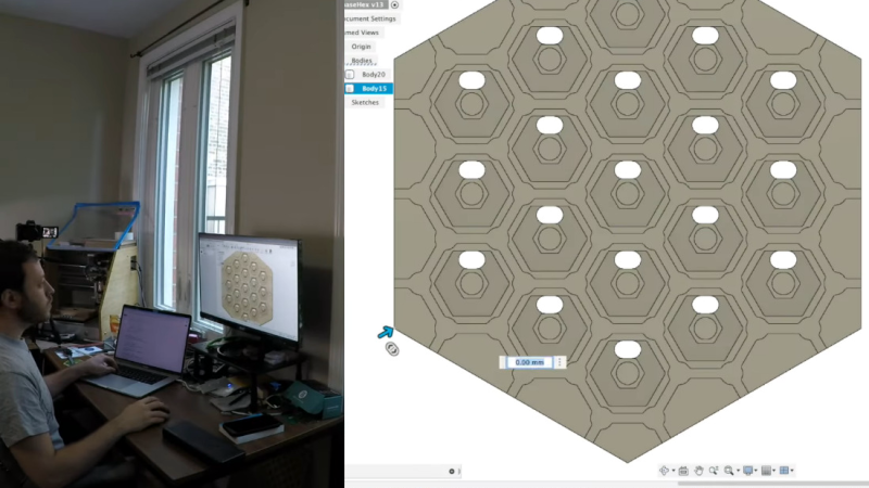
One of the things that makers sometimes skip over is the design of the project that they’re creating. Some of us don’t do any design at all, we just pants it. The design part of making something can take quite a while – there is sketching to do, as well as 3d-modelling and PCB creation. [Sam March] wanted to try and create something interesting where he did the design in a single day. The result is, or will be, a 3D printed, electronic, Settlers of Catan game board.
As [Sam] goes through his thoughts while working, we get a good, quick, overview of the design process. It’s good to see that it can be done but this is only the design stage – [Sam] will post the video of the build for this design once he’s received the PCBs and the board has been printed. Take a look at some other Settlers of Catan projects on the site, like this 3D Catan board or shock your friends with this Catan timer.


“Some of us don’t do any design at all, we just pants it”
The word design is overrated sometimes…
You can buy a regular bathroom accessory that costs an acceptable amount of money.
And you can buy some expensive model of the same item that wears the label “design” as if it was made by the gods themselves. But it’s pretty annoying if the latter starts rusting as soon as it gets wet.
What I’m trying to say is that the word “design” is sometimes heavily overrated.
You may “design something badly” of “pants it” perfectly. Either way, it’s the end result that counts.
Regarding the project…
I designed something in one day… yeah right.
You drew up some plans in the first day of the project (most likely where thinking about what you were going to make days before, doesn’t that count too). A design isn’t finished as soon as you want to stop thinking about it, it’s finished when it is completely build AND fully functional. Because the moment you really start making/testing/using it you will encounter some problem, which the true engineer always want to solve. Which is a major part of the design too. You cannot pretend that that will not happen or always can be prevented. The fact that PCB’s never arrive the same day (unless you make them yourselves) makes the entire concept of designing something in one day highly questionable. And if it has software/firmware in it, well then it is never really finished, is it. Feature creep is some horrible monster that is hard to defeat. And then the power issue… wires are cumbersome, batteries are always too small energy consumption is in many ways underestimated… wireless eventually requires wires too and connectors and ahhhh… rabbithole after rabbithole
I just wanted to share these thoughts…
Regarding the project, I’m not familiar with the game, but it seems like fun, I’ll have to dive into this game soon. And a project with lights in it, is always a fun project in my book.
Hi Jan,
Sam (creator) here! I appreciate the feedback. I guess whenever I talk about projects, I tend to talk about them in 2 phases, first a design phase then a build phase.
The design phase is where I do all the architecting/thinking, the modeling, the PCB and schematic design, etc.
The build phase is where I machine/3d print parts, I assemble circuit boards, I flash code.
As crazy as it sounds, this entire project was designed in one day! I debated whether or not I should upload the entire gopro time lapse uncut so people could see. It just felt a little boring to watch.
You’re absolutely right that when you get an idea, it’s impossible not to think about it for days or weeks leading up to the project, but I intentionally tried to pick a project that day to cut down on “pre-thinking”. My goal with this “design in a day” series for the future is to actually let the public decide the project for me the day of (obviously all files will be open-source). This first project was more of an introduction to the series.
As for the build, I actually got the circuit boards this passed Wednesday and things are up and running! I am actually editing the video for it as I type this message to you!
Hope you like the work
Sam,
Looks like a fun project, but I must have missed the discussion on how you were going to route the wires between the boards/modules, and how it was going to be programmed and powered. Which I think is a key issue. Also, I see how you make the boards covering five sides of each hex, was that to leave the room to route the wires between them?
As for the covers, are you going to include diffusers to make the light glow evenly around the ring?
I guess what I’m saying is that you have some videos of the design process, but not really any talking about the design tradeoffs and why you went with the board design you did. And you also glossed over the MCU choice as well. Was that one you were familiar with already, and which JCLPCB had in stock?
I also wish you had talked more about the dimentions as well. I must have missed that discussion.
But for sure an interesting project. Though I suspect the programming part will take longer than expected to get just the right look. And heck, how is the die roll input into the system? Do you have wireless die which automatically input the data?
So maybe that’s more of what I think the design part of the job means to me, what is your exploration of the problem space, not quite so much the implementation of your solution. Does that make sense?
Cheers,
John
Absolutely! I love the feedback. This was only my second video ever, so I am very much open to constructive criticism.
I was trying to walk the line between being TOO much content and enough to give some ideas of what was going on. I will try and answer your questions here though!
First up, you are right, the 5 sided hexes are to allow wire routing. In the 3D modeling you can see I punch some holes all the way through the wood in each hex. The wires will enter those holes and daisy chain down along a spiral. The next video where I do the build will make that more obvious.
The covers will be a clear acrylic that I’m going to sand down to give it a cloudy diffuser look, so again, right on the money!
As for the MCU, it was both a part I had experience with (firmware and hardware wise) while being one fo the few MCU’s JLC had left in stock. Sometimes the best part is the part you can get!
Dimension wise, the whole board is about 2ft across at its widest.
The dice rolls (for now) will be a button press. The MCU board has an input pin for a NO switch. I was actually talking to my SO about making some BLE dice that can pair with the board in the future.
Hopefully that clears some stuff up!
Best,
Sam
Thanks for the update! Makes alot of sense to hear what you’re doing. It will be neat to see how it works in practice. I suspect that you’ll need more aggressive diffusion for a nice even glow.