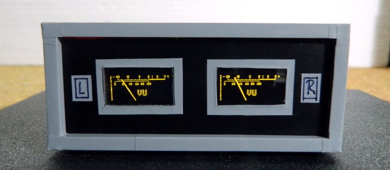
Looking for a digital recreation of the classic analog volume unit (VU) meter? If you’ve got an Arduino, a few passive components, and a SSD1306 OLED, then [mircemk] might have the answer for you. As you can see in the video below, his code turns a handful of cheap parts into an attractive and functional audio display.
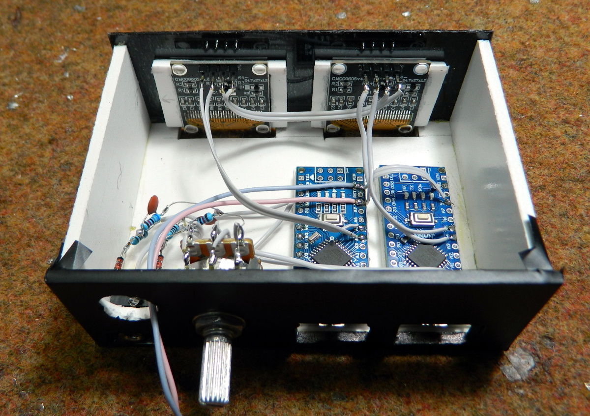 The project’s Hackaday.IO page explains that the idea is based on the work of [stevenart], with code adapted for the SSD1306 display and some tweaks made to the circuit. While [mircemk] says the code could be modified for stereo as long as the two displays don’t have conflicting I2C addresses, he decided to simply duplicate the whole setup for each channel to keep things simple. With as cheap as some of these parts are nowadays, it’s hard to blame him.
[mircemk] has provided source code for a couple different styles of VU indicators, the colors of which can easily be inverted depending on your tastes. He also clarifies that the jerky motion of the virtual “needle” seen in the video is due to the camera; in real-life it sweeps smoothly like the genuine article.
Much like the project that aimed to recreate authentic “steam gauges” with e-paper displays, this as an excellent technique to file away for use in the future. Compared to authentic analog gauges, these digital recreations are quicker and faster to implement, plus going this route prevents any antique hardware from going on the chopping block.


Nice looking but a lot f electronics to replace a simple meter. These may cost a bit less to make, but I am old school and I like the look of large real meters. The pictures of this have to be life size or a tad bigger than life size.
“… as the two displays don’t have conflicting I2C addresses …”
Individual data lines for every display and a common clock line combined with some bit-banging can resolve this issue. These displays only need a full I2C implementation if you want to read the frame buffer.
Last time I wrote my own ssd display driver I remember reading all serial interfaces could do was write to the controller, no reading. To read you have to use one of the parallel interfaces. A bit of a bummer since it’d make bitmasking possible without having to double buffer.
I should try this on one of my SSD1322 256×64 OLED displays. Should be able to fit two VU displays side-by-side on a single display.
I’ve thought about this for some time, and always come to the same conclusion: stair-stepped needles and pixelated text just don’t cut it.
So the good news is that some VU meters had a needle that stayed flat, due to the needle being bent 90° at the end and the axis being behind the scale also at 90°.
Or Vertical, instead of horizontal.
That would at least fix the needle, not sure on the text, maybe some kind of filter to smooth the edges by interpolating.
Kool idea, as long as they don’t put it in a museum display, I hate it when the museums have fake stuff like that.
A “real” VU meter isn’t just something that measures sound levels — it has to have very specific needle response time and damping requirements.
Came here to say just that. If the ballistics is not present in the response it’s not a real VU meter.
Nowhere does the article say it’s a “real” VU meter, just that it’s analog style digital recreation of an vu meter. I agree though that adding some physics emulation in software will go a long way to improving such a digital vu meter. I think I’ve seen one or two projects that do exactly this in the past.
The OLED update rate seems to be a bit slow. Perhaps try the fast I2C bitbanging method descibed here: https://bitbanksoftware.blogspot.com/2018/05/fast-ssd1306-oled-drawing-with-i2c-bit.html
This is why I much prefer the spi interface with these displays, can easily push a few MHz as opposed to the 400kHz I believe the I2C interface is limited to.
try the ESP8266. its amazingly fast on i2c compared to the atmel 8bit cpus.
I used to prefer spi on atmel but now that I see how fast updates are via esp, no reason to go back. plus, esp gets you web access to it! just write to it via cgi or better yet, websocket. that’s a stream. stream updates to it over wifi. I’ve done it in fact and its super fast.
Last I checked the oled is limited to 400kHz max on the i2c bus. That’s why I usually go with spi for driving these screens.
I2C also supports 1Mbit, 1.7Mbit, 3.4Mbit and 5Mbit, although wether the OLED controller does is a different matter. SPI is less hassle and easier to drive multiple devices as it relies on a separate device select line though. All but this line can be shared over multiple devices.
IIRC screen is limited to 400kHz, definitely spi is the better choice imo.
That’s soo cool! Reminds me of the early 90s! My mom got a wrist watch as a giveaway (via mail).. It had a digital clock face with an LC display, you know, the old vintage type without individual “pixels”, but predefined symbols. Well, the cool thing is was – that watch simulated an analogue clock! With clock fingers! Boy, this was mind blowing at the time! 😀
I noticed a line of noise pixels on the left edge of some of the demo photos.
I know what causes that. you picked the wrong display type or size. 128 vs 132 and .96 vs 1.3″. sh vs ssd (or something like that, for model names).
just change the types and you should see the line noise disappear. sucks that there are 2 ‘cpu types’ but there are.
Possible, or the wrong initialization driver was selected. I know selecting the ssd1306 configuration on a sh1108 display will incorrectly send the charge pump on command (only valid for the 1306) which will be interpreted incorrectly for the wrong controller along with the display addressing commands being slightly different. IIRC the 1108 wraps around/increments the pixel address automatically at the end of a row, but the 1306 requires a command to go to the next row (or something like that). This would explain the junk data at the left size of the display (basically command data being interpreted as display data).
Maybe a better choice would have been a Blue Pill rather than an Arduino?
It has two hardware I2C ports built in, runs faster and can be had for the same or less than the Mini.
Wow those 0.96″128×64 OLED displays he’s linking to at Newark are out of stock and cost USD $21.59 each. Last time I looked on Amazon I could get five I2C 0.96″ OLED SSD1306 displays for $14.99 (ASIN B08QJ7BL3R), that’s $3.00 each.[1]
Why are two microcontrollers being used? The I2C displays maybe? Instead there may be a way to change an address resistor or jumper on those OLED displays so you can put two of them on a single I2C bus, or use an I2C mux chip, or use a software I2C port(s) (e.g. Softwire for Arduino[2]), or use a micro with more than one I2C port (e.g. ESP32 w/2xI2C, or Blue/Black Pill STM32F103C8T6L w/2xI2C). Using the ESP32 will also allow the device to operate over WiFi and/or Bluetooth.
* References:
1. Five Pieces 0.96 Inch OLED Module 12864 SSD1306 Driver I2C
https://www.amazon.com/Frienda-SSD1306-Self-Luminous-Compatible-Raspberry/dp/B08QJ7BL3R
2. SoftWire, Software I2C Library
https://www.arduino.cc/reference/en/libraries/softwire/
Viele interessante Beiträge und Kommentare. Aber vielleicht ist mal jemand dabei, der das VU-Meter mit der Bogenskala genauer anschaut so wie ich. Dann sollte auffallen, dass die Skalenbeschriftung leicht durcheinander ist. Den zugehörigen Code kann ich leider nicht korrigieren, aber der “Konstrukteur” hat vieleicht die Möglichkeit, es zu tun. Wäre ganz toll! Bei der Linearskala ist alles o.k.
Vielen Dank und macht weiter so tolle Sachen mit Arduino und Co.