One of the best things about adulthood is that finally we get to, in most cases, afford ourselves the things that our parents couldn’t (or just didn’t for whatever reason). When [Yakroo108] was a child, Walkmans were expensive gadgets that were out of reach of the family purse. But today, we can approximate these magical music machines ourselves with off-the-shelf hardware.
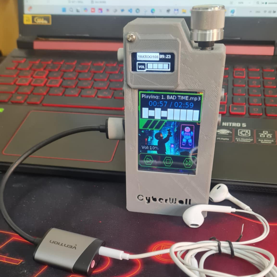 Besides the cyberpunk aesthetic, the main attraction here is the UNIHIKER Linux board running the show. After that, it’s probably a tie between that giant mystery knob and the super-cool GUI made with Tkinter.
We also like the fact that there are two displays: the smaller one on the SSD1306 OLED handles the less exciting stuff like the volume level and the current time, so that the main UNIHIKER screen can have all the equalizer/cyberpunk fun.
Speaking of, this user-friendly GUI shows play/stop buttons and next buttons, but it looks like there’s no easy way to get to the previous track. To each their own, we suppose. Everything is enclosed in a brick-like 3D-printed enclosure that mimics early Walkmans with orange foam headphones.
If you want an updated Walkman with keyboard switches (who wouldn’t?), check this out.