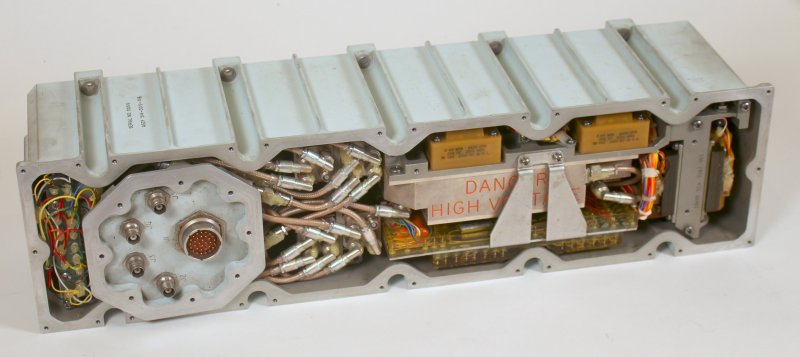
When the Apollo astronauts made their way to the Moon, their communication equipment had a transmission power of a mere 20 W, which the sensitive receivers back on Earth managed to pick up. But this isn’t just any amplifier, it’s a Traveling Wave Tube amplifier (TWT), as [Ken Shirriff] explains in a recent article.
The most fascinating thing about these TWTs isn’t just their role during the Apollo missions, but the fact that even today this type of vacuum tube is still among the most efficient and compact types of RF amplifier. As a result today’s high-tech satellites still commonly feature these devices.
As always, [Ken] entertains and enlightens us with how the TWT and the rest of the amplifier system worked.


Thank you for a nice article. However I am still mystified as to how an em wave is amplified by an electron stream. If I took regular coax and pumped an rf signal into it while running a current through the shield, would I get an amplified rf signal out? And why do they have to be traveling at the same speed? I am missing something fundamental. An electron stream is dc current, right? That’s the same thing as a spark which is what was first used to make radio waves (Hertz? Right- the guy not the car company). So an electron stream should be broadcasting a bunch of noise.
“If you took regular coax…” answer is no. Per the article’s description, there’s an electron gun, like in a CRT. Not down a wire, but literally shooting it down a tube. But electrons don’t travel at c. “The trick is to put the RF signal through a helix, wrapped around the beam.” (This is NOT equivalent to a coax shield!) “Because the RF signal travels through the long helix rather than in a straight line, its path through the tube is slowed. With the proper helix design, the RF signal and the electron beam travel at approximately the same net speed down the tube, allowing them to interact.” The power of the electron beam amplifies the RF signal.
In article around LINAC you get Infos how Wave accelerator Tubes Work.
Just do a YouTube search for how a Klystron works, that will explain it for ya
You know how a regular tube works, right? A positive voltage on the plate attracts electrons from the cathode. Then a much smaller voltage on the grid controls them and thus you get amplification. The plate is close to the cathode and you get a lot of capacitance which limits the RF frequency you can use. So they ran out of gain about VHF frequencies.
TWTs work the same way, except the electron stream goes through a longer tube so no frequency limit. You make the electrons go down the pipe using magnets, permanent for small tubes, a solenoid for big ones. You need a lot of voltage to coax them down there. Usually the cathode is at a high negative voltage, and the anode is at ground.
So how do you get gain? Look at it from the electron’s view. It’s accelerated to the collector by high voltage so it’s moving quite fast. the drive signal is fed into the slow wave structure and it travels near the speed of light, but since it goes down a helix it goes as fast as the electrons down the pipe. So that electron has a while to interact with the voltage on the helix. It slows down if it’s a negative voltage, speeds up if positive. Note that this voltage stays constant all the time that electron is traveling down the tube; like “bullet time” but they’re traveling together. The slow electrons bunch up and the fast ones catch up to them, so you get alternating high and low voltages at the end of the tube. Put a window on the end of the tube and voila, there’s your RF. After spending this long time interacting, the gain can be pretty high.
This amplification isn’t terribly efficient and the beam that isn’t coupled out as RF hits hard against the collector. You can improve this by sorting out the electrons by kinetic energy. Without a magnetic field focusing them into a stream, they spread apart and the slow ones spread faster. The really hot ones go straighter, and you can put a collector in front of them that has a voltage near the cathode voltage, instead of at the anode voltage. That slows them down considerably. This is called collector depression, and the amount of power you save is the collector depression times the beam current that hits it. You can put multiple collectors at different voltages to collect different speed electrons, at the expense of multiple power supply voltages and more complicated tubes. You might get 40% efficiency out of a 2 collector tube and 60% out of a 5 collector tube.
Klystrons work the same way as TWTs except the slow wave structures aren’t connected. Magnetrons work like klystrons except they’re a torus instead of a line. And magnetrons work like whistles. Story for another day.
The more I learn about the moon landing technology in retrospect, the more amazed I am that they pulled it off.
Yup, I’ve seen one of the Apollo Command Module capsules in person at a museum (I don’t remember which, it was a long time ago) and I was both horrified and amazed that we sent people to the moon with 60’s tech. It is truly amazing that they were able to pull it off.
There’s a “small” group of people who still doubt it, haha. Among other things of course lol. Maybe because the “learning” part is not their strength :)
Its not the technology part that I’m maazed about. Its have three guys live in a VW bug for the whole trip, and poop into a ziploc bag.
Had to use traveling wave amplifiers at some point. It was a glancing blow. They’re clearly witchcraft. Run for the hills!
Agree with anyone who at first glance refuses to believe these things can work. But have had a beer and not a coffee so won’t attempt to explain my jumbled explanation of the magic.
I like to think of these like undulators but the magnets are replaced by the magnetic component of another wave, a bit like resonant constructive interference. Almost akin to laser cooling. I love the simplicity of these things, personally I find this sort of physics quite beautiful. More so that this can be applied to other forms of wave and scaled to any frequency.
Witchcraft, yes, that could explain it. Apparently there is a helix of wire, that somehow guides the wave. Like some kind of inside out waveguide..
Hmm. Turns out, the RF does actually travel as current in the wire helix. That current creates a magnetic field within the helix, no witchcraft needed (NWN), that causes the flying electrons to speed up or slow down (NWN) so as to match the signal in the helix. It’s called velocity modulation. Now these bunched electrons represent a modulated current that then induce current back into the helix (NWN), transferring energy from the beam to the helix (NWN). Hence the amplification.
Obligatory nod to Arthur Clarke.
It was a travelling wave tube because it was microwave, and there weren’t many options in the sixties.
The work on radar during WWII caused a great leap forward, they neededhigher and higher frequencies, and devices that worked up there. So not really a scaling of existing tubes, but a new branch. Ironically, transmitting was easier than reception, they went back to cat’s whiskers as mixers in the receivers, semiconductor diodes like the 1N21, which led to the 1N34 and transistors after the war.
20W for Apollo was good, if you think about ham radio moonbounce with 1Kw of power, the signal is miniscule when it hits the moon, and even smaller back on earth. Starting with 20W on the.moon made it a whole lot easier.
I’m pretty sure the command module was used as a relay, thiugh I can’t remember what happened when it was on the other side. So maybe I’m remembering that the LEM was a repeater for the astronaut’s radios. CQ magazine in 1968 had an article, maybe two parts, about the communication system for Apollo.
It was 12years after Sputnik, I assume the design came a few years before Apollo 8. Not a lot of options, not even that much in space at the time. But probably another leap forward because of the space program.
Ask, and ye shall receive as they say. There is an “Apollo Experience Report” written in 1972. This one details the Lunar Module telecommunications. There’s so much amazing material available from the era. This is fascinating reading.
https://ntrs.nasa.gov/api/citations/19720023255/downloads/19720023255.pdf
According to the publication cited above, the Lunar Module S-band transmitter employed Amplitron tubes, also known as cross-field amplifier (CFA) tubes. According to the rather short Wikipedia article about CFA tubes, two CFAs could be connected to the same waveguide with one powered down and not interfering with the active tube. The paralleling capability would have simplified the waveguide plumbing, presumably saving weight which was a paramount concern for the LM.
CFAs were developed at Raytheon in the 1950s derived from experience in building magnetron tubes. CFAs were originally designed for high power, high bandwidth applications. The LM downlink to the manned space flight network was only about 18 Watts in the S band and had two primary subcarriers of 1.024 MHz for PCM data and 1.025 MHz for analog voice imposed on a 2282.5 MHz carrier. Apparently wide bandwidth and high power were not as important as the simplified redundancy capability in making the choice for employing Amplitrons in LM S-band transmitter.
On the other hand, the Command Service Module employed traveling wave tubes in its transmitter.
Let’s hear it for thermionic radiation folks!
I was just thinking this. Lol. More like an intro to an article. I always try to be very kind to people putting their work out into the world, but that reference will get a hearty chuckle out of me every single time. Well played.
While the physics of things like this are now pretty well understood, I imagine some of the early inventions in the field were likely the result of wiggling different experimental setups and seeing a needle jump and then trying to figure out how to reproduce what just happened, understand and perfect it
1. The command module was not used as a link for sending back the audio and video from the LM. The CFA’s on the LM were 18 watts and therefore could send signals directly back to the large earth station antennas
2. The microwave tube industry is alive and well. There are still many applications where solid state cannot compete with tubes in terms of power, cost and efficiency. The power source in all the microwave ovens are magnetrons
4. IVEC is the International Vacuum Electronic Conference which is held every year
https://ieeeivec.org/ivec_2021_info.html
5. Two References for further reading
A. Scott Gilmour Jr, “Klystrons, Traveling Wave Tubes, Magnetrons, Crossed-Field Amplifiers, and Gyrotrons” Artech House, 2011.
R. G. Carter, Microwave and RF Vacuum Electronic Power Sources, Cambridge University Press, 2018
6. Basic theory behind most all tube operation is well understood. Today, simulation based design is used extensively in the tube industry just as in all other modern engineering discipline. Also, the tube factories use a high degree of automated assembly and process control to generate high yields.
An interesting thing about the twts that went into space for satellites and probes in the 60’s and 70’s was the use of Platinum/Cobalt magnets to focus the beam. They were the strongest Magnets at the time. Weight was more important than cost at that time.
Thomas Brown
Hughes Electronics (Retired)