Tubes! Not only is the internet a series of them, many projects in the physical world are, too. If you’re building anything from a bicycle to a race cart to and aeroplane, you might find yourself notching and welding metal tubes together. That notching part can be a real time-suck. [Jornt] from HOMEMADE MADNESS (it’s so mad you have to shout the channel name, apparently) thought so when he came up with this 3-axis CNC tube notcher.
If you haven’t worked with chrome-molly or other metal tubing, you may be forgiven for wondering what the big deal is, but it’s pretty simple: to get a solid weld, you need the tubes to meet. Round tubes don’t really want to do that, as a general rule. Imagine the simple case of a T-junction: the base of the T will only meet the crosspiece in a couple of discreet points. To get a solid joint, you have to cut the profile of the crosspiece from the end of the base. Easy enough for a single T, but for all the joins in all the angles of a space-frame? Yeah, some technological assistance would not go amiss.
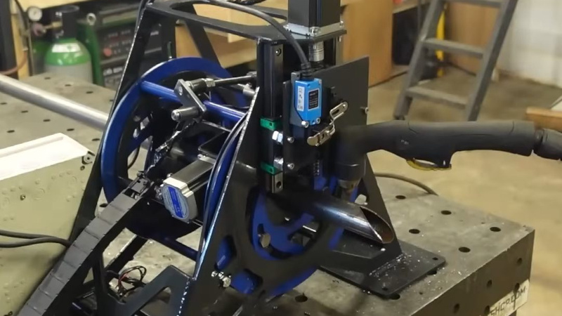
Which is where [Jornt]’s project comes in. A cheap plasma cutter sits on one axis, to cut the tubes as they move under it. The second axis spins the tube, which is firmly gripped by urethane casters with a neat cam arrangement. The third axis slides the tube back and forth, allowing arbitarily long frame members to be cut, despite the very compact build of the actual machine. It also allows multiple frame members to be cut from a single long length of tubing, reducing setup time and speeding up the overall workflow.
The project is unfortunately not open source– instead [Jornt] is selling plans, which is something we’re seeing more and more of these days. (Some might say that open source hardware is dead, but that’s overstating things.) It sucks, but we understand that hackers do need money to eat, and the warm fuzzy feeling you get with a GPL license doesn’t contain many calories. Luckily [Jornt] has put plenty of info into his build video; if you watch the whole thing, you’ll have a good idea of the whole design. You will quite possibly walk away with enough of an idea to re-engineer the device for yourself, but [Jornt] is probably assuming you value your time enough that if you want the machine, you’ll still pay for the plans.
This isn’t the first tubing cutter we’ve featured, though the last build was built into a C (It wasn’t open-source either; maybe it’s a metalworking thing.)NC table, rather than being stand-alone on the bench like this one.
Thanks to [Shotgun Moose] for the tip! Unlike tubing, you can just toss your projects into the line, no complex notching needed.


I found a YT video that was pretty similar a couple of months ago and sent it to a friend, because he has a fiber laser. The issue with plasma torches is they leave a not great surface finish and you sometimes have to do a fair bit of cleanup, but a fiber laser has a lot of advantages as regards both finish and not overheating the adjacent tubing and possibly cooking your tubing rollers.
However, as my friend pointed out, this project is mostly about the pretty amazing software this guy has created for this, and replicating that in a reasonable timeframe is much more challenging than the hardware.
Wow!
Comment system is screwy, I wasn’t replying to this comment.
I will refrain on commenting on the mechanical and control aspects here (I am handicapped by experience in the field and not wanting to pay the vig for missing details) and say that I kind of like it.
Optimal? no.
Reasonable? maybe.
A negative for me is the fixed radial orientation for the torch. It is desirable to be able to fit the joint with controlled contact and bevel for the weld.
An extra axis to tilt the cutter would be great! OTH, the alternatives available to hobbyists– a hole saw in a jig or an angle grinder and a vise– don’t give the perfect bevel, either. I imagine for a homebuilt airplane you’d go the extra to get a perfect fit with hand files, but I think most bubbas with dune buggies just weld a thicker bead to make up for it.
a perfect fit is actually detrimental to the weld penetration—it should be a canyon that’s filled with the weld, rather than a weld on top of an empty ‘perfect’ contact area
Please site professional references to support your argument…
Look for any instruction on pipeline welding. There is always a gap for the root pass. The weld are most often x rayed to look for 100% penetration. The petroleum and welding certification agencies could be cited but no knowing which country you need compliance data for prevents comprehensive listing. In the US you would look to API and NWS.
I’ll toss my 2 cents in here. I’ll start with my credentials.
Journeyman Red Seal Pressure Welder – 25 years
B620 Certified Welding shop owner, qualified to work on dangerous goods highway tankers.
I hold 23 (I think) engineered weld procedures.
If penetration is the goal such as in pressure vessel (all pressurized piping systems are pressure vessels) a but joint with no bevel prep is unacceptable according to any code out there as it does not guarantee a full penetration weld with a 0 defect internal root pass. The thicker the material the more bevel is required.
Now when dealing with thin wall tubing you want the fit to be as tight as possible and for the fillet weld to be the reinforcement. Especially with chromoly. as the goal isn’t to hold pressure but to create a structurally rigid structure. Any weldment on thin wall tubing will put more reinforcement than there is thickness in the tube material. So what you need to worry about is your HAZ ( heat affected zone) and notch effects due the structure being put under a dynamic load. A tight fit and proper weldment negates both of these. The tighter fit requires less weld time, and therefor, less heat input reducing the HAZ and the chance of cracking that an excessive HAZ introduces. The tight fit, and the proper weldment negate the notch effect that can cause cracking.
Projects like this are an amazing way to showcase new designs, ideas, and skills. The guy can design, engineer, prototype, wire, code, weld, fabricate, and trouble shoot his own projects. Mad respect. We need more of this. I can guarantee that 90% of the nay-sayers here can’t do half of that.
Don’t see why this is 3-axis if it’s just cutting the tube… it’s just making cuts on a 2d surface (the tube’s surface)? Extend/retract and rotate should be the only axis needed? Or do you need to do multiple passes at varying depths with a plasma cutter?
On very thick tubes, you might need multiple passes, but it goes through in one shot in all the footage he shares. So that’s a good question.
I think the z-axis on the plasma cutter is mostly just to adjust for tubes of different sizes. That doesn’t seem strictly necessary, though; there’s no reason that couldn’t have been linked mechanically to the gripping mechanism. That free up an axis for adding bevels like [cliff claven] suggested in an earlier comment.
Square tube capability necessitates the third axis.
Plasma cutters need a Z axis to control the arc. In theory, on a perfectly round, centered tube you could pre-adjust the tip height, but in practice you need a feedback-driven motion—which gives you the capacity to cut square tubing as well.
Had a chuckle at chrome-olly vs chromoly.