We’ve all found ourselves swimming amongst too many similar-looking USB cables over the years. Some have all the conductors and functionality, some are weird power-only oddballs, and some charge our phones quickly while others don’t. It’s a huge headache and one that [TechKiwiGadgets] hopes to solve with the Arduino Cable Tracer.
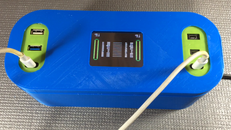
The tracer works with USB-A, Mini-USB, Micro-USB, and USB-C cables to determine whether connections are broken or not and also to identify wiring configurations. It’s built around the Arduino Mega 2560, which is ideal for providing a huge amount of GPIO pins that are perfect for such a purpose. Probing results are displayed upon the 2.8″ TFT LCD display that makes it easy to figure out which cables do what.
It’s a tidy build, and one that we could imagine would be very useful for getting a quick go/no-go status on any cables dug out of a junk box somewhere. Just remember to WIDLARIZE any bad cables you find so they never trouble you again. Video after the break.


No Micro USB-A port?
My dad just bought a new ebike which was advertized as being able to charge phones. On checking the day before leaving on a multi-day trip, he found out the port was Micro USB A. Whenever you search for that the first links immediately say “Ebike phone charge cable”, but ordering online took tpo long. Yet several consumer electronics stores said USB Micro A doesn’t exist.
Turns out that the “not included” cable was included anyway.
I have never, ever seen a micro-A plug, even though they are defined in the standard. Every case of a usb peripheral with a micro plug has just used the micro-B instead. (I have seen mini-A, but back when those were current, almost nothing did usb host that couldn’t just use full-size sockets anyway, apart from my old linux palmtop.)
Me neither, so it has become a semi-propietary cable – althoug the chinese and bicycle dealers now sell off-brand cables.
My ex-girlfriend had a webcam that had a mini-A-female connector (on the device), which I also have never seen elsewhere (and I think A-plugs are only meant for PC’s and charging devices, not for “slave” devices)
I still have a couple devices(junk drawer) that use those. It was so rare I had not even considered it might be part of the standard.
I think they’re used with really old otg stuff too, like I think the older Jetson Tegra dev boards have a mini-AB port for this purpose and come with a mini A to full size A adapter.
I was looking for good graphics to print out for USB cable bin labels and one said MicroA is deprecated because everyone used B, and yes, out of nearly 100 mixed cables, zero Micro A.
I have a TI Nspire calculator from around 2011. This has a combo Micro B/A port. It came with a Micro B to Micro A cable. With that you could connect it to another calculator and the one with Micro A connected became the host for programming. Only time I’ve ever seen one too!
I think my single Micro AB cable is what I use in these situations. I didn’t even know what it was until I ran across an old Micro A port device.
Oddly I recall it coming as a standard cable with a Micro B device.
Of course, I don’t think I realized that until I looked it up based on your post!
Great for identifying power only cables
USB requires negotiation to pass more than 100 mA, or measuring the resistance between the D wires to identify a high power charger.
A power-only cable is ironically only able to pull the lowest available power out of the USB port, unless it is paired with a device that will skip the negotiation and pull high current anyways, and a non-standard charger that won’t shut down for over-current. In other words, they’re basically useless.
So why do we have them?
Power-only cables usually connect the D+ and D- together at the device side connector, indicating a charging port.
If the device assumes a charging port because of the cable, but it’s not actually connected to a charging port, trying to draw high current would shut the port down and pop an error message on the PC.
The dedicated charging port indicator is less than 200 Ohms between D+ and D-. The “charge only” cables that I’ve seen are open circuit for the data lines – not connected. This should cause the device to fail negotiation and default to the lowest current.
“Why do we have them?” CHEAP…..
It was already on my to-do list to search AliExpress for exactly this. High-end braided cable seemed like the least likely fault in a chain of components, but turned out to be the problem. Need to check them all…
But how would you identify thick from thin cables? With cheap ones the charging current can be low due to savings on copper…
I once had a cheap cable for charging in the car – discharge from running the Navi was faster than the poor charging.
You could possibly try measuring the resistance of the cable? You’d have to know its length too I guess, but I’m assuming cheaper cables have higher resistance per cm.
I’s not per se the the thickness or length that matters. It’s better to measure the ability to dissipate heat – you could do that by putting the cable under high stress and measuring the resistance (voltage drop) directly and after a while.
I’d be worried about letting out the magic smoke from cheap cables!
If it gives up that easily, it’s better off in the trash.
Just measure the voltage drop, the Arduino has ADC. You’ll probably need to add a Mux chip like a CD4066.
Using a Mega is overkill, I’d have used a smaller Arduino (easy if muxed) and added as many sockets as possible. USB, ethernet, audio, RCA, DC, etc.
An adjustable constant current source and measuring the voltage drop should be good.
I have this gizmo. USB-A to mini only, but already very convenient.
https://www.tindie.com/products/nerfhammer/is-it-me-or-is-it-usb/
I do wish that cable testers that did more than just continuity were more readily available. Like, I know with these digital cables there’s more than just continuity that matters, you’ve got like characteristic impedance, cross talk or noise isolation, probably some kind of frequency response thing. But it’s all far too close to RF black magic for me to know how to build one. At least with coax cable I figured out I probably could test them with a VNA if I wanted to
Very nice and very useful. And nicely executed. It would be rather great to also have Cat5 Ethernet to tell the null from the patch or whatever they call them. And though we don’t use them much anymore, a DB9 for serial cables to show which version.
Maybe I’m an idiot but I thought that the “null” is called “crossover” wiring and that it doesn’t matter whether its a patch or a crossover is used if both ends support Auto MDI-X.
I’ll need to check the details, but wouldn’t this mark E-marked usb-c cables as bad? E-marked cables aren’t exactly a 1-to-1 connection, least on a few of the pins (cc1 and cc2 come to mind).
Are there commercial versions of this? I’d happily pay $150 for a finished unit. The build in the post is pretty involved, beyond the time I have for such a project.
I too have been frustrated with trying to find good quality USB/iPhone charging cables, so I created this ESP32 based cable tester: https://forum.swmakers.org/viewtopic.php?f=9&t=2452 It checks for continuity of the data wires with a LED readout and measures the GND/VBUS resistance with data being displayed on the OLED screen. It currently uses three banks of 2512 resistors to place different loads onto the cable and measures the voltage drop and therefore resistance of the cable.
Could you shut up and take my money. Plz? ;)
Could add max current testing till voltage goes out of specs.
I wonder if this guy is a fencer. This is like an upgraded body cord tester.