Open source pick and place machines have come a long way in the past years, but are not necessarily worth the setup time and machine cost if you are only building a few PCBs at a time. [Nuri Erginer] found himself in this situation regularly, so he created PnPAssist, a “smart” build platform to speed up manual PCB assembly. Video after the break.
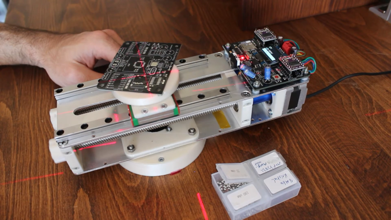
The PnP assist consists of a small circular platform that can automatically translate and rotate to place the current footprint in the middle of the platform, right in the center of your microscope’s view, and a laser crosshair. The entire device can also rotate freely on its base to avoid contorting your arm to match the footprint orientation. Just export the PnP file from your favorite PCB design software, load it on a micro SD card, plug it into the PnPAssist, and start assembling. The relevant component information is displayed on a small OLED display right on the machine. [Nuri] has also created a component organizing tray that will indicate the correct compartment with an RGB LED.
Below the build platform, a 3D printed gear is in contact with a pair of parallel lead screws driven by stepper motors. The relative motion of the lead screws allows the platform to rotate, translate, or both. This arrangement also means the machine is a lot more compact than a conventional XY-table and can be packed away when not in use. The base is held firmly in place on the workbench with a set of suction cups or screws. Power is provided through the fixed base using a slip-ring, so there are no cables to twist up as you spin the machine around.
We can certainly see this machine being a massive help on any small electronics assembly job, especially considering the fast setup time and relative simplicity. It will also work well with the 3D printed component dispensers or component turntable we featured in the past.
![]()


Brilliant
Whoa, this will be absolutely awesome when you have a ton of analog circuitry with a lot of different value parts. No more triple check and still getting some resistor wrong. No search for the spots.
It’s a neat device in a small gap between manual and fully automated pick and place. I don’t see a use for it in my workflow, but i guess if it helps you, that is good enough.
What i would deffinately want to improve on is the user interface to control the robot. Have the display and control buttons on theyr own, to position them better on the workplace could be a good idea. I guess you were kinda worried about the wiring on the desk becomming a mess, but for me having an easy access to the controls and the display in a place and angle where it’s easy to read and reach would be preferred.
The way he uses one end switch for two axis is quite clever! And overall this looks like a really nice design.
Thinking of building just the turntable as that would be a great start. Just rotating the pcb to match the parts is a big step forward.
Awesome. Chuck in a bit of machine vision, and it’ll be able to rotate to align to the component you’re holding in the tweezers!
Would anyone like a reverse lookup feature?
Install a known board, and manually adjust a specific part into the crosshairs, and read the part details from the display?
It is a very nice invention. I would like to see a wireless way (e.g. Bluetooth) to download the settings instead of inserting SD card. I think the two side tape is OK only as an option but there should be a way to secure the board so that it won’t move due to bumping, becoming less sticky or perhaps weight of components (if more board is hanging off platform). I assume this is to be used by boards that have paste on the solder pads?
Well done! It’s very elegant, the opposite of the usual rat’s nest…
However, if the main function is to designate the location of the next component to be placed, I wonder if it wouldn’t be even simpler to simply attach a laser to a couple of gimbaled servos, next to the information screen on the component being placed, and hang the whole thing on the same stand as the microscope.
Of course, this machine does more than designate the location: it brings the PCB location back to the same position under the tweezers. But if the hand has to move anyway to pick up the next component, the advantage is less… Only experience can tell if it is worth it.
In any case, the analysis is relevant: for a few PCBs, setting up a pick and place machine is too time-consuming, and beyond that, an external service will probably be more efficient and more economical. Hence the interest to think about this kind of solution, for us Makers.
Translated with http://www.DeepL.com/Translator (free version)
I propose a very simple improvement:
Extend the device a little, and install a second rotation axis between the same two screws. This axis would carry a carousel of boxes for the components, which would allow to bring successively under the tweezers or the suction cup, first the good component, then the PCB in the good place. The only thing left to do would be to manage the orientation manually.
Also, I think linear rails are overkill: for such low loads, 3D printed bearings sliding on precision cylindrical rods would work just as well, and the mechanical architecture would be even simpler: no need for parallel milled plates, the rods also acting as frames. With a few small 3D-printed parts, the whole thing would be extremely economical.
This is definitely an excellent and fruitful idea! Bravo! …et Merci!
I recall back in old days in electronic production lines they used pointing light where to place the component (also orientation of a IC) combined with light on the bin to pick from.
So this could also be made by a small LED video projector beaming to the top of the PCB and a Raspberry PI to convert the placement table to a video with a cross and another cross where to pick the component
I have used this setup with an old mercury lamp projector.
I want one! Please put it up on Crowd Supply or Kickstarter made with injection molded parts.
This is fantastic. With a pivoting vacuum pick ‘n place tool to hold the part in place for soldering it would be much faster than setting up a fully automatic machine.
Or attach a laser to a 3D printer. Put the PCB on the print bed.
Seems very complex, slow, and has the distinct downside of the PCB not staying in the same place (ignoring rotation) which means rapid placement is difficult.
I would maybe use a down facing projector above, and a hand-rotating table (lazy susan) below.
The projected image would be black except for the point where the component should be placed, or something like that.
When you rotate the rotation is detected by the RasPi attached to it and the image being projected is rotated as well.