 Although jet engines are theoretically quite simple devices, in reality they tread a fine line between working as intended and vaporizing into a cloud of lethal shrapnel. The main reason for this is the high rotational speed of the rotors, with any imbalance due to poor manufacturing or damage leading to undesirable outcomes. It’s for this reason that [AlfMart CNC Garage] on YouTube decided to spend some quality time building a balancer for his DIY RC turbine project and making sure it can prevent such a disaster scenario.
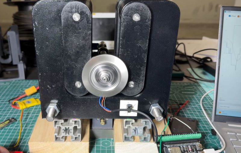
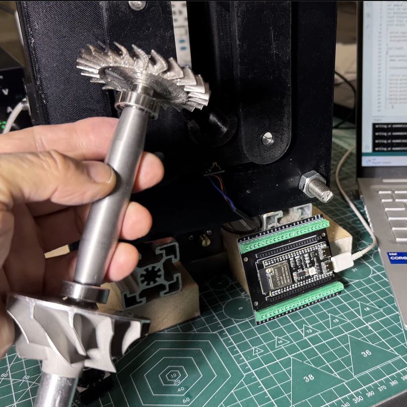
In the previous part of the series the turbine disc was machined out of inconel alloy, as the part will be subjected to significant heat as well when operating. To make sure that the disc is perfectly balanced, a dynamic balancing machine is required. The design that was settled on after a few failed attempts uses an ADXL335 accelerometer and Hall sensor hooked up to an ESP32, which is said to measure imbalance down to ~1 mg at 4,000 RPM.
A big part of the dynamic balancing machine is the isolation of external vibrations using a bearing-supported free-floating structure. With that taken care of, this made measuring the vibrations caused by an imbalanced rotor much easier to distinguish. The ESP32 is here basically just to read out the sensors and output the waveforms to a connected PC via serial, with the real work being a slow and methodical data interpretation and balancing by hand.


You might want to fix the headline to indicate milligrams rather than megagrams…
Though capital G is not grams either. It’s the universal gravitational constant. The unit MG would have a value 6.674 x 10⁻⁵ Nm2/kg2 (crossing fingers that the formatting worked)
And it didn’t. Pretend you can see the superscripts. Hey, HaD, it would be nice to have a guide somewhere that tells us what tags work in the comment system this month…
+1
Hall sensor seems an odd choice to measure rotation instead of a photosensor. A sharpie mark would do a lot less to unbalance it than a protrusion or magnet.
Unless you magnetized the thing itself I guess.
and you can mark on both side and just devide by two the rpm if you care about sharpie ink unbalancing…
then you won’t know which side the imbalance is on
Magnetizing a single blade of the turbine can be done, too. And it won’t add any mass to the turbine…
Except for the fact that inconel 718 is nonmagnetic.
You don’t need to magnetize it.
If your material is ferromagnetic, ou can simply put a magnet behind your Hall sensor.
When the blade or teeth (like in a gear), is passing in front of the sensor (and thus in front of the magnet), it will concentrate the magnetic flux.
The hall sensor will then measure this increase in magnetic flux.
I saw it’s use in an internship long time ago, so I don’t recall all the details. I believe we didn’t even use any magnet and it worked flawlessly to detect the teeth of a gear in a gearbox.
But maybe the gears where magnetized without me knowing it..
Except for the fact that inconel 718 is nonmagnetic.
Even if it were ferromagnetic with 22 tilted, curved, and overlapping vanes spinning at 4000 rpm Im not so sure you would get a decent read with a hall sensor.
engine crankshaft sensors are usually variable relutance not hall
I once worked on the software to balance helicopter rotors, (and also detect worn bearings and broken teeth within the engine by looking at the speed of the rotor).
He’s making the assumption that if the rotor is out of balance the extra mass is on the compressor (vanes) end, and that’s not necessarily true. What he should really do is have 4 accelerometers on the four “feet” of the test rig, and then he can detect imbalance at both ends of the rotor.
Depending on your level of math, with four sensors you can detect not only the angle of the imbalance, but where along the shaft to take away mass for optimum balance.
And I might suggest spinning up the rotor using compressed air (or magnetic fields), then doing the balance measurement with the air turned off, while the system is spinning down, with no interference from the motor.
Then instead of looking at the oscilloscope, you can take repeated measurements over many revolutions, and average. This will reduce noise, while making any imbalance stand out.
I’ve occasionally considered building a system for balancing spinny things, but everything is a project nowadays. To get anything up and going takes a large amount of time and effort just to build the tools you need.
My first thought was “Why not use compressed air instead of a BLDC motor?”. Also this guy might be a good engineer, but he didn’t really explain what he was doing, how and why…
getting a perfectly even distribution of air across the entire turbine surface isnt nearly as easy as just spinning it with a motor. Any imbalance in airflow would throw off the measurements and would cause him to make adjustments that would further imbalance the turbine.
you could spin it up with air and do measurement on the run down
except that you want a known and constant speed, not a constantly diminishing one.
You can measure changes of forces for each rotation over the wide range of speeds, and just plot them in relation to position. Repeat this a few times to accumulate more data points and average for higher resolution. For example if you need to have a solid measurement at 1kRPM, just spin it up above that speed, note the values around 1kRPM point, spin it up, and repeat 15 more times, add the results and divide by 4. The whole process can be automated by mounting a compressor nozzle on the frame and adding a solenoid valve that will operate it…
PWalsh: You can do it with just two sensors: One at each end of the shaft is necessary and sufficient to get phase and amplitude at each end, giving you the mass and location required for balance. That was standard practice for balancing a 800 kg rotating platform we built. At peak production we had one per day come off the line. The measurement and analysis was automated and the recipe was given by the computer “place mass A on studs B at depth C”, where “C” was number of ‘flats’ (1/6 turn) of the nut on the 1/2″ studs: this determined the axial location of the mass. The balancing operation in x,y,z took just 2 or 3 iterations — a few minutes.