Surface mount devices have gotten really small, so small that a poorly timed sneeze can send your 0603 and 0402 parts off to live with the dust motes lurking at the edge of your bench. While soldering such parts is a challenge, it’s not always size that matters. Some parts with larger footprints can be a challenge because of the pin pitch, and getting them to land just right on the PCB pads can be a real pain.
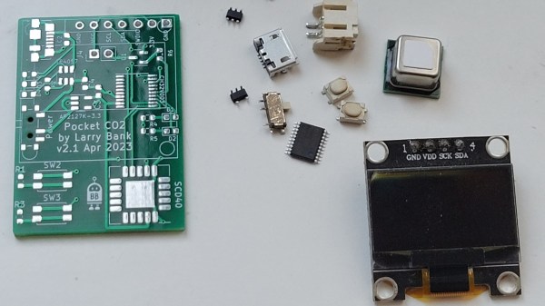
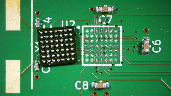
To fight this problem, [rahmanshaber] came up with this clever custom PCB fixture. The trick is to create a jig to hold the fine-pitch parts securely while still leaving room to work. In his case, the parts are a couple of SMD ribbon cable connectors and some chips in what appear to be TQFP packages. [rahmanshaber] used FreeCAD to get the outline of each part from the 3D model of his PCB, and KiCad to design the cutouts; skip to 7:30 or so in the video below if you don’t need the design lesson. The important bit is to leave enough room around the traces so that the part’s leads can rest of the PCB while still having room to access them.
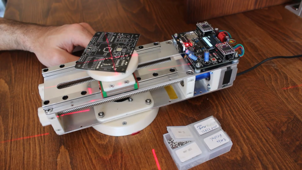
Using the fixture is pretty intuitive. The fixture is aligned over the footprint of the part and fixed in place with some tape. Solder paste is applied to the pads, the part is registered into the hole, and you’re ready for soldering. [rahmanshaber] chose to use a hot plate to do the soldering, but it looks like there’s enough room for a soldering iron, if that’s your thing.
It’s a simple idea, but sometimes the simplest tools are the best. We’ve seen lots of other simple SMD tools, from assembly jigs to solder paste stencil fixtures. Continue reading “Custom PCB Is A Poor Man’s Pick And Place”