Drones have become the standard for moving aerial camera platforms, but another option that sees use in the professional world are cable cameras. As an exercise in integrating mechanics, electronics, and software, [maxipalay] created his own Cablecam.
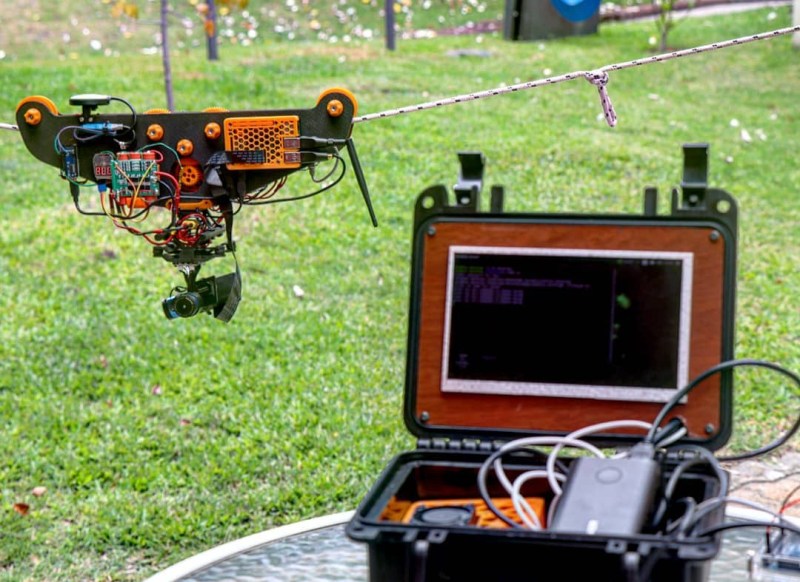
Cablecam is build around a pair of machined wood plates, with some pulleys and motor reduction gearing between them. A brushless hobby motor moves the platform along the rope/cable, driven a drone ESC. Since the ESC doesn’t have a reverse function, [maxipalay] used four relays controlled by an Arduino to swap around the connections of two of the motor wires to reverse direction. The main onboard controller is a Raspberry Pi, connected to a camera module mounted on a two-axis gimbal for stabilization. A GPS module was also added for positioning information on long cables.
The base station is built around an Nvidia Jetson Nano connected to a 7″ screen mounted in a plastic case. Video, telemetry and control signals are communicated using the open-source Wifibroadcast protocol. This uses off-the-shelf WiFi hardware in connectionless mode to broadcast UDP packets, and avoids the lengthy WiFi reconnection process every time a connection drops out. The motion of Cablecam can be controlled manually using a potentiometer on the control station, or use the machine vision capabilities of the Jetson to automatically track and follow people.
We’ve seen several cable robots over the years, including a solar-powered sensor platform that resembles a sloth.


I’m trying to understand why it requires four relays to reverse the motor, and hackaday.io is such a pain to navigate I didn’t find the answer there. They’re SPDT relays — I’ve got the same board in front of me. I’m trying to figure out how to wire it up to use four relays. I keep coming up with two relays left over. Unless it also has to switch hall sensors too?
Probably to make something like a H-Bridge, so the cables can be switch even when current is flowing.
Maybe when you send 0 as the speed control to the ESC it still powers the coil and you can’t just use 2 relays otherwise it will make a short circuit.
It’s a bad idea to switch direction while actually driving the motor because a) the inertia could torque off the load and b) the sudden change in currents could result in an inductive kickback and burn the driving transistors in the ESC
Most likely they’re using the relays as SPST relays (even though they are SPDT). It would require 4 of those.
+1 !
From TFBP (The Fine Blog Post): “Since the ESC doesn’t have a reverse function, [maxipalay] used four relays controlled by an Arduino to swap around the connections of two of the motor wires to reverse direction.”
From Maximilano’s IO writeup: “For the power train I used a brushless motor made for hobby drones, and an ESC. The ESC was made for multicopters so not exactly meant to work on this project. It had no reverse, so I implemented a polarity switch using 4 relays with an Arduino. So every time the robot changed direction, the relays switched polarity of two motor wires.”
Yes… but it’s not clear why you would need four SPDT relays to change the polarity of two wires, when two is the usual number required. TFBP did not elaborate.
Some hobby motor ESCs do in fact have a reverse function. Just a matter of software.
Also, as I start to recall things from my drone days, many ESCs have a programming menu that can be used to change things like whether or not it has reverse. Of course, without proper instructions, it can be impossible to know what you’re doing. The menu is usually accessed by flipping the throttle back and forth in a certain way during startup, and the only output you get is a varying number of “beeps” from the motor.
Or just don’t use a drone ESC… car model almost always support reverse
At a guess, this may be so you can “break before make” to avoid creating a sudden short to the motor controller?
I haven’t clicked the link so could be talking nonsese of course ;)
Damn HaD comments – this was meant to be a reply to @Paul.
lol @ the comments on reversing the motor. After reading the article I felt like commenting on how either using a RC car ESC with reverse or using an air ESC with firmware for ‘3D’ flying, but then thought it was a little unfair to the project to focus on something so pedantic. Then I scrolled down and saw the HaD Army was already on the same warpath.
For real though, neat project. I understand that part of this project was to have auto tracking, so it is apples and oranges, but I’ve made something similar to this that was fully manually controlled with RC stuff I had laying around. RC car ESC, motor, RX/TX, and wheel for motion. DJI FPV camera, VTX, and goggles for video. I had mine run on paracord due to its abundance and length vs cost, but sag was an issue with longer runs.
For all of you raging about polarity reverse:
Yes, I know there are ESCs with reverse, yes I could have flashed another firmware to allow for reverse.
I did this with what I had laying around, the project didn’t justify buying an esc just to gain a reverse function.
The four relays are used to totally disconnect the motor from the esc, and then reconnect with polarity changed. As C. Scott Ananian said, these are SPDT but are being used as SPST.