It’s no surprise that many hardware hackers avoid working with AC, and frankly, we can’t blame them. The potential consequences of making a mistake when working with mains voltages are far greater than anything that can happen when you’re fiddling with a 3.3 V circuit. But if you do ever find yourself leaning towards the sparky side, you’d be wise to outfit your bench with the appropriate equipment.
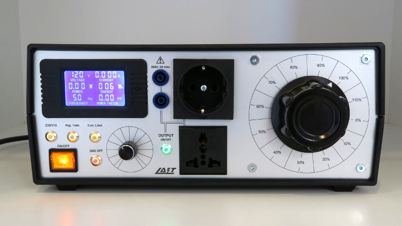
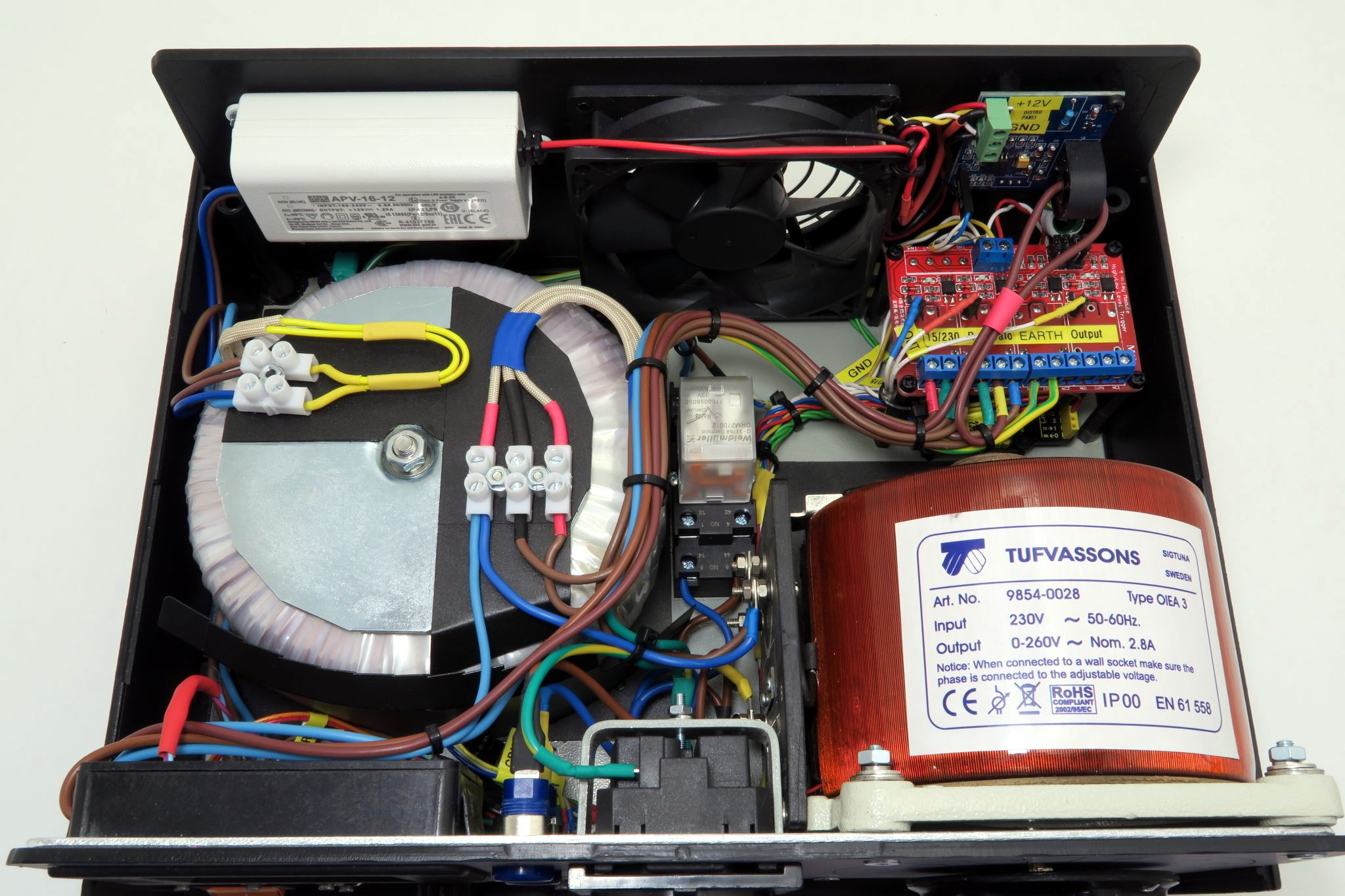
Take for example this absolutely gorgeous variable isolation transformer built by [Lajt]. It might look like a high-end piece of professional test equipment, but as the extensive write-up and build photographs can attest, this is a completely custom job. The downside is that this particular machine will probably never be duplicated, especially given the fact its isolation transformer was built on commission by a local company, but at least we can look at it and dream.
This device combines two functions which are particularly useful when repairing or testing AC hardware. As a variable transformer, often referred to as a variac, it lets [Lajt] select how much voltage is passed through to the output side. There’s a school of thought that says slowly ramping up the voltage when testing an older or potentially damaged device is better than simply plugging it into the wall and hoping for the best. Or if you’re like Eddie Van Halen, you can use it to control the volume of your over-sized Marshall amplifiers when playing in bars.
 Secondly, the unit isolates the output side. That way if you manage to cross the wrong wire, you’re not going to pop a breaker and plunge your workshop into darkness. It also prevents you from accidentally blowing up any AC powered test equipment you might employ while poking around, such as that expensive oscilloscope, since the devices won’t share a common ground.
Additional safety features have been implemented using an Arduino Uno R3 clone, a current sensor, and several relays. The system will automatically cut off power to the device under test should the current hit a predetermined threshold, and will refuse to re-enable the main relay until the issue has been resolved. The code has been written in such a way that whenever the user makes a configuration change, power will be cut and must be reestablished manually; giving the user ample time to decide if its really what they want to do.
[Lajt] makes it clear that the write-up isn’t meant as a tutorial for building your own, but that shouldn’t stop you from reading through it and getting some ideas. Whether you’re in the market for custom variac tips or just want to get inspired by an impeccably well engineered piece of equipment, this project is a high-water mark for sure.


Man that is a nice build!
Second that!
Usually cobbled such a thing together with a Variac and a separate isolation transformer. When you want to float the output on top of another PSU, or centre tap the ground in a way the output wasn’t designed to play along with, this type of thing really comes into its own.
It’s a bit small though. My Variac is usually used to control quite heavy loads (2 to 3 kW), and is wired to provide 0 to 110% of mains voltage. Which if used at the right time of day, when we’re getting 250V on the road, gives 275V, though I have seen it peak above 280 V unloaded onto a true RMS Fluke. This makes universal motors go really well. Rather like lightly supercharging the lawnmower.
Yes it’s very clean inside and out
Very nice, but there is no need for a custom built 1:1 isolation transformer. If you’re having difficulties finding one, simply take any two identical transformers of the required VA rating, and connect the low voltage secondaries back to back so that one steps down the mains voltage to LV while the other steps up the LV back to mains voltage, albeit double isolated.
Or, if you don’t mind a little loss, take any transformer that has two 120V primaries (put in parallel for 120VAC or series for 240VAC), just use one for primary and the other for secondary. There is a little voltage loss, but you can boost that with the original secondary if it’s close the the amount you need to add.
Your suggestion must be accompanied with the following caveat:
A true isolation transformer usually hosts primary and secondary windings on separate bobbins… or where coaxially wound, the windings are grouped separately, with added insulation between the primary and secondary coils.
The benefit of this construction is that the failure of either coil–through overheating or insulation failure– is not likely to result in the loss of coil-to-coil isolation… which is a safety issue and the whole point of this exercise.
In a transformer with two primaries, those windings most likely will exist on the same bobbin, are wound together as a pair, or in any case are located closely together without concern for additional insulation between them. This is because the expectation at design time was that the potential difference between them will never be significant.
Yes, you can treat one winding as a primary and one as a secondary, and your idea will work. And yes, by definition, one winding is “isolated” from the other.
However, in this case, if one coil overheats to the point of compromising its insulation, the coil-to-coil isolation will also likely fail… which defeats the whole point of having a 1:1 transformer in the first place.
Obviously there are thousands of different transformers made by thousands of manufacturers. If you can verify that the primaries on a two-primary transformer reside on separate bobbins (I have seen some small box-core transformers wound that way) my guess is that you’d be OK. Barring that, I would not recommend your idea for the construction of any daily-use instrument or device.
Bottom line: Whether or not you can safely use a given transformer in the manner you suggest depends upon the specific details of its physical construction.
The isolation is a good feature here. The point that needs attention in a Variac is the power wiring. Variacs with a power cord, housing, and a switch have one flaw. One side of the power is passed though. The other side goes through a switch that breaks the input line. If it happens to be wired or plugged in so that the “Hot” is on the neutral or ground side of the inductor, there is no switch for that side and it is passed out to the load, which might mean the chassis or other parts you can touch. It also passes through the inductor to the wiper and feeds the hot side of the load as well. So everything gets energized at the level of the source power. This has been an ongoing hazard in research and education labs for 70 years or more.
In the old days when US plugs had no polarity this was a serious issue and it still is when people rewire or replace power cables. Or when they use a Variac in a custom circuit. I don’t know in what ways it is possible to get in trouble with an isolated setup (if any) so I’ll leave it at that.
I understand the idea, but it is not how it works.
The total power of the transformer is predetermined with several aspects. Some of them being size of the core and thickness of wire used for windings.
In this build 600W transformer was used. And if you short circuit its secondary side, it can’t pull much more than its design lets it. Not for long at least.
To prevent it from overheating an inline fuse of 4A is used. So even that fuse will burn out before the wall socket fuse trips or transformer burns.
So yes, the isolation transformer does prevent popping wall fuse if it is purposely designed.
Another objective here is to isolate the faulty load from line voltage to prevent RCD protection from going off.
p.s. if it wasn’t like that no arc welder would ever work ;)
if you don’t mind a little loss, take any transformer that has two 120V primaries (put in parallel for 120VAC or series for 240VAC), just use one for primary and the other for secondary.
This trick might work (with the isolation caveats mentioned above), but only in the 10% of the planet that uses 100-120V supply.
In most of the world (230-240V), if you try this trick the transformer core will saturate and you will end up with a smoking heap of dead transformer (if the fuse or breaker doesn’t save you first).
In a way of clarifying, the variac and/or the isolation transformer on their own do not prevent popping a breaker and plunging your workshop into darkness. They do float the power supply, so if you touch the live while grounded through your chair or desk, the current will not flow through you—but it will flow between the floating live and floating neutral, and draw the corresponding current from your lab supply circuit, possibly tripping the breaker
The OP did include a current control and shutoff, so that it CAN prevent tripping the breaker, but this is a special feature of their specific system.
What I came to say.
Personally, I prefer the incandescent globe trick when powering up possibly faulty devices. Shameless self plug: http://levysounddesign.blogspot.com/2016/04/mains-current-limiting-bulbs.html
You mean this trick?
http://www.repairfaq.org/sam/smpsfaq.htm#smpstslbt
(just wanted to post a/the(?) proper original source link)
Nice build, nice to have all in one place. Why relays instead of SSRs if he was hoping for reliability?
Relays are just as reliable as SSRs, if they aren’t switched too often.
Relays positively isolate.
SSRs have the potential to have leakage currents.
All that guys before me said plus:
For this purpose, relays need to cover 0-280V and 0-3A.
SSR-s don’t have adequate output voltage rage, and minimum switching current of cca. 10-15mA on 200V.
And they are quite expensive.
When I was playing with model trains in the 1960s, Lionel used variable isolated AC to power their “0” gauge systems. I believe they could provide about 18 V.
Yeah. My first bench supply! I added first one diode then a bridge, no cap. Many things have some caps in place even if they run on a battery. It didn’t go to zero just 6 volts to 12-15 or so. The cap got put in eventually.
That is a work of art!
This got me thinking about two items that a lab should have that can be found on eBay and in surplus. One is a good auto-transformer like a Variac, especially if isolated.
The other is a Sola constant voltage transformer. Yes, they actually produce a constant voltage as the input varies and good for testing. They are especially popular in countries where the power gets extended beyond the rated capacity of the cables and changes in load have large effects on the voltage for the terminal users. There are large regions in Mexico and other countries were the local “electricians” will run cables from power poles int through a window for you. https://www.reddit.com/r/WTF/comments/14l1z2/india_laughs_at_your_power_poles/
When I built mine years ago I used two identical Power Transformers from guitar amps to make a 1:1 isolation transformer and used a Variac. I later added a dim bulb and additional switches to select the dim bulb, variac and bypass. I need to build a new case for it and put it on my equipment rack.
Really peace of art. Nice to see someone like Lajt to share his knowledge to the rest of us. Was checking his page and was quite surprised with quality of content. Keep up the good work. Some of comments were funny to read as loads of guys here want to look smart behind keyboard but comment buy one. This was custom build and the quality of craftsmanship is astounding to me. Again hats of to the guy who build it.
When compared to the typical mains-connected stuff found on HaD, this is a freaking gorgeous work of art that would probably conform to most of the stuff in the IEC61010-x and the IEC61558-x series.
The only things I did different in my variac box (other than that does 2.5kVA, but is 3x the size of this and not as elegant) is to put a properly rated NTC across the relay in lieu of the resistor in the soft start circuit, and to disallow microcontroller control of anything other than to display real and true P, V, I, PF, and coil temperature. There are some other stuff, but at the power level for this thing, the design decisions are ok.
This device has dangerous flaws. The earth contacts on the output are connected to earth on the primary side and this connection is switched with a relay. Not exactly what one expects from an isolation transformer. Better not use it when repairing a TV with a hot chassis.
Contrariwise! First, no hot-chassis appliance is going to have a grounded plug on it. Hot chassis devices have always been designed to prevent electrical contact by the user with any part of them. And second, this is one of the BEST uses for an isolation transformer, because by isolating the line, you CAN safely ground the chassis, making it possible to make ground-referenced measurements when working on it.
Nope, that’s a common misconception. If you connect the hot chassis to the PE of your house wiring and accidentally touch the other end of the secondary, you get the full blast because the RCD/GFCI cannot see the fault current and won’t trip. The safe way is to keep the complete work environment floating; connect the hot TV, all test gear and the soldering iron to the isolated secondary, tie their earth connections together but do not connect them to the primary PE.
The solution for that isn’t to leave everything floating, but to use a GFCI outlet as the output from the isolation transformer. I can’t stress this enough: if you leave a high voltage circuit completely floating, all you can be sure of is that you won’t KNOW when there’s a ground fault, and what OTHER points of the circuit will then carry lethal potential. I’m sorry, but yours is the common misconception. I know this because it’s what I USED to believe, until I was shown the errors of my ways. As soon as you connect an oscilloscope to two points on your “floating” circuit, one of those points is grounded. Or do I misunderstand, and you are also floating the oscilloscope?
The purpose of isolating a hot chassis circuit isn’t to do away with ground and make everything floating, but to set what YOU want to be the ground reference instead of relying on the several self-proclaimed electricians that have worked on the wiring in your house.
What are you people talking about? This is not consumer/appliance equipment. Where is the requirement in IEC61010-1, IEC61558-1, or even EC61558-2-6 for anything to do with consumer/residential GFI stuff or whatever?
Geez people, freaking holy molasses with buttermilk banana pancakes. Pay attention to the intended scope of the equipment’s end use. Otherwise, please feel free to not comment on regulatory matters if you have no accredited experience in compliance engineering.
So what you’re telling us is that you put molasses on pancakes. That’s all I need to know. Good DAY, sir.
Nice build but not exactly “one of a kind”. Such a project has allready been described in the QEX March 2015 issue http://www.arrl.org/files/file/QEX_Next_Issue/2015/Mar-Apr_2015/Drell.pdf
It’s definitely a nice bench equipement, and, since I built one, I can’t hack without it
;-)
Marc
It should be noted that there *are* variacs with an isolated output winding. I have an old Knight-Kit model 660 battery eliminator (an adjustable 0-20v power supply) which uses such a variac.