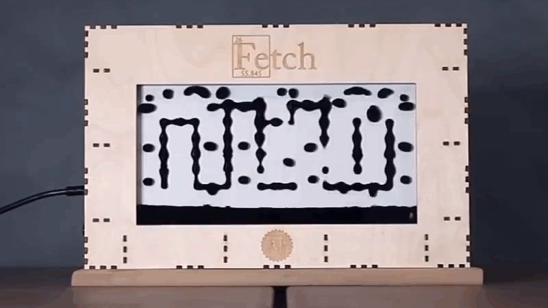
In 2019 [Simen] and [Amud], two students from the University of Oslo, set out to design a unique open-source display. The result was Fetch, a display that uses electromagnets to suspend ferrofluid on 252 “pixels” across the screen. After some delays due to COVID, they have recently unveiled version 2.0 of the display on their project’s page.
While the duo managed to overcome the mechanical challenges associated with using ferrofluids fairly easily, they were quickly bottlenecked by their electronics. The use of electromagnets holding up a liquid presented a unique challenge; the magnets could not be switched off, even for a millisecond, or else the “pixel” would fall down to the bottom of the screen. That immediately ruled out any sort of multiplexing and meant everything would have to be driven in parallel. As if that wasn’t already difficult enough to work around, the effect of having multiple electromagnets activated next to each other would change how the ferrofluid flows. This meant that the strength of each electromagnet would have to be adjusted based on what is currently being displayed, rather than just being on or off.
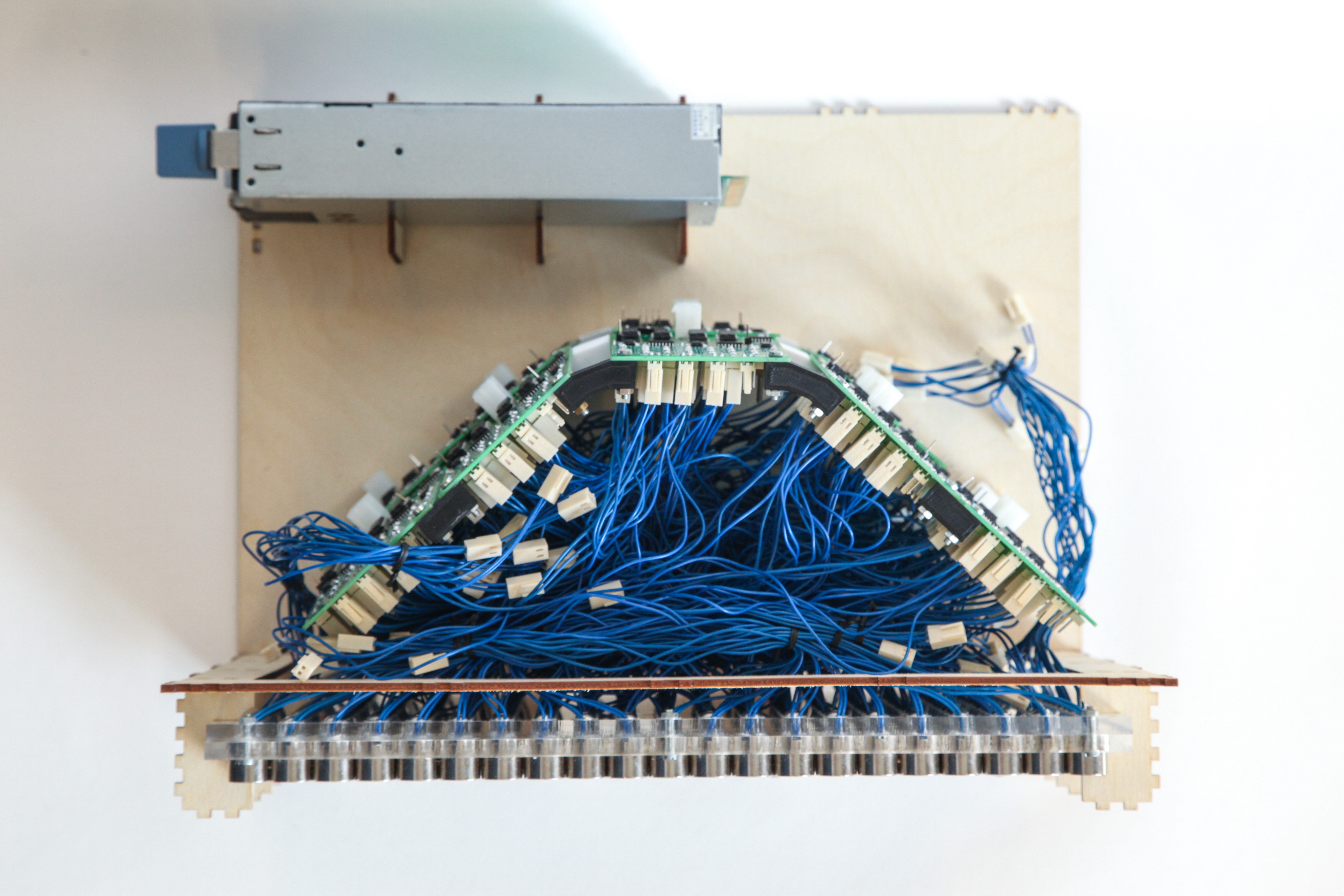
All of this, paired with other overhead like generating pulse-width modulation for the inputs, was just too much for a single microcontroller to handle. So, the pair set out to design a better version of their electronics that would offload a lot of the hard work. At the same time, they decided a bit of mechanical optimization was in order; they redesigned the boards to be longer and thinner, allowing them to fit cleanly behind the row of electromagnets they controlled.
The new boards feature a PCA9685 IC, which allows for the control of up to 16 channels of 12-bit PWM over i2C, perfect for the size of the display. Since this IC can’t source enough current to drive the electromagnets, it was paired with a ULN2803 Darlington Transistor Array, capable of delivering up to 500mA to each electromagnet.
With prototypes in hand (and a few bodge wires here and there), [Simen] and [Amud] had the new driver boards running beautifully, displaying text in a mesmerizing way that no ordinary display could match. Watch the video after the break for a demonstration of the new controllers in action, as well as a deeper dive into the process of developing them.
Want to learn more? Check out our previous article about Fetch! Or if you’re looking for another cool way to use ferrofluids, how about making it dance in a custom speaker!
[Main image animation is slowed by a factor of 3]


Curious why it wasn’t done with some serial-input latches w/ transistor of some kind to deal with the current?
Ah– I need to learn how to read better…. my bad :-)
Since I will likely never get around to playing with this, why not try using ALNICO electropermanent magnets to allow multiplexing? Although, this probably wouldn’t allow for variable strength magnetism at the magnets.
Does anyone have any info on the longevity of the ferrofluid when it’s used like this? I remember hearing some murmurs of the tank becoming a black cloud of gunk after an amount of time.
Aww yis, I have been interested in ferrofluid clocks since that one guy made a really nifty machined mechanical one, the. Saw their rendition. Glad they are still working on it / improving!
I don’t see why multiplexing is not possible. Electromagnets are in principle inductors, they resist change in current. If you equip them with free-wheeling diodes, you could maintain a magnetic field with a PWM. If the average current turns out to be too low, just increase the driving voltage. If the losses in the free-wheeling diodes turn out to be too high to achieve practical frequencies and voltages, replace the diodes with MOSFETs.
This seems possible. if you use an extra diode in series with each magnet. If you use MOSFETs instead of diodes, you need extra drive electronics, that does not really make sense. In that case you could just use this MOSFETs as individual PWM drivers and forget multiplexing.
But if you use e.g. 12V as drive voltage, the extra diode losses are only a few percent.
The driving circuit for the MOSFETs would require one signal per each row – not per each MOSFET, so it would still be simpler than driving each coil individually. But you’re probably right that there would be not much to gain from this.
There are a few issues:
– The PWM frequency has to be high enough that the next refresh arrives before the inductor current drops below the threshold to attract the fluid. Even with the free wheeling diode, the inductor current would follow an exponential decay (due to losses). This means high interrupt frequency or need some hardware assist.
– There is probably a lower limit on the duty cycle that is needed to maintain the current threshold. This limits to the number of inductors that can be shared in the multiplexing scheme.
– You probably need some way to sample the inductor current or need to do some calculations to figure out the duty cycle needed from off to on and what’s needed to maintain current above threshold.
BTW there is a way that a multiplexing scheme could work. You could need each coil driven by its own MOSFET. The MOSFET gate is driven via a large analog MUX. The MUX sequentially goes to each MOSFET to drive them high/low. Each MOSFET can maintain its states (for a short time) as they have gate capacitance on the order of nF holding the charge – sort of like a DRAM cell that hold their values, but need frequent refresh. You could increase this with an external capacitance.
You can have fading effects by using PWM to each MOSFET thus controlling the gate voltage. This however give very limited control that works around the MOSFET threshold VTH and the MOSFET will get hot dropping the voltage.
You could replace the whole with emulation running on LCD :D
Please, this is not for you, it’s that your comment gave me an idea for an insult:
“You could replace your whole brain with emulation running on a Tamagoshi.”
This thing is so cool!
Awesome work! Just out of curiosity…how much current does the electromagnet draw at 100% duty cycle? Does the darlington driver get very hot?