Screenshot of debugging the Wokwi Arduino simulator

Digging Into An ATtiny Simulator Bug With GDB

Being able to track down a bug in a mountain of source code is a skill in its own right, and it’s a hard skill to learn from a book or online tutorial. Besides the trial-by-fire of learning while debugging your own project, the next best thing is to observe someone else’s process. [Uri Shaked] has given us a great opportunity to brush up on our debugging skills, as he demonstrates how to track down and squish a bug in the Wokwi Arduino simulator.

A user was kind enough to report the bug and include the offending Arduino sketch. [Uri]’s first step was to reduce the sketch to the smallest possible program that would still produce the bug.

Once a minimal program had been produced, it was time to check whether the problem was in one of the Arduino libraries or in the Wokwi simulator. [Uri] compiled the sketch, loaded it onto a ATtiny85, and compared the behavior of the simulator and the real thing. It turns out the code ran just fine on a physical ATtiny, so the problem must have been in the Arduino simulator itself.

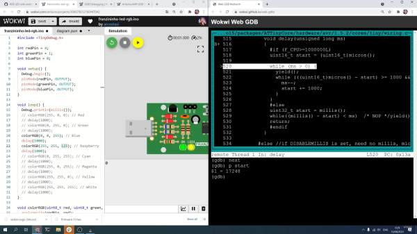
To track down the bug in the simulator, [Uri] decided to break out the big gun—GDB. What follows is an excellent demonstration of how to use GDB to isolate a problem by examining the source code and using breakpoints and print statements. In the end, [Uri] managed to isolate the problem to a mis-placed bit in the simulation of the timer/counter interrupt flag register.

If you’d like to see more of [Uri]’s debugging prowess, check out his dive into an ATtiny’s write protection and configuration fuses. If you’ve been wowed by the power of GDB and want to learn more, check out this quick tutorial!

Continue reading “Digging Into An ATtiny Simulator Bug With GDB”

Making High Quality Copies Of Existing Parts Using A Silicone Mold

3D printing has made it incredibly easy to produce small runs of plastic parts, but getting rid of the 3D printed look can be tricky and time-consuming. When you need a smooth and polished finish, or you want to make exact copies of an existing injection molded part, casting resin parts in silicone molds is an excellent option. [Eric Strebel] has plenty of experience with the process, and demonstrates it in detail while creating copies of violin chin rests that are no longer in production. It’s an interesting application, where 3D-printed layer lines are not just an aesthetic issue, but something that would irritate the user’s skin if present.

Creating silicone molds requires a bit of forethought about the mold design. You want to select the split line to make it as easy as possible to remove the finished parts, while also placing the resin pouring sprue and vents to prevent air bubbles from getting trapped in the mold. In [Erics] case, it’s impossible to use a simple planar split line, so he mounts the master part on a block of wood and uses cardboard and modeling clay to create a volume where the second side of the mold will protrude in the first side. It’s important to note that sulfur-free clay must be used, otherwise the silicone might not cure.

One side of the silicon mold is cast first, and after curing it is placed back in the mold box with the master part to allow casting the other side of the mold. At this point [Eric] super glues the sprue-former and vent rods to the master parts before molding the second side. A release agent consisting of petroleum jelly and naphtha is added wherever the two sides of the mold will touch, to prevent them from sticking together.

Bubbles are your enemy while resin casting, so ideally you need a vacuum chamber to degas the silicone and resin before casting, and a pressure chamber to allow the resin part to cure. While pouring the silicone for the molds, the mold box is placed on a vibration table to allow any bubbles to rise to the surface. While the entire mold-making and molding process is time-consuming, the copied parts are almost indistinguishable from the original.

[Eric] has also shown us how to make much larger silicone molds in the past. If you find yourself making lots of different-sized mold boxes, it might be worth building an adjustable mold box.

Continue reading “Making High Quality Copies Of Existing Parts Using A Silicone Mold”

A Simpsons TV For A Golden Age

While the pace of technology continues to advance at breakneck speed, certain things in the past are left behind largely subject to the whims of nostalgia. Televisions, for example, are lighter, cheaper, and bigger than they were in the early 90s, but they did have a certain design aesthetic that doesn’t exist anymore. Meanwhile, Simpsons episodes have been (arguably) on the decline since the golden age of the 90s, so [buba447] decided to combine these two facets of a nostalgic past into a custom TV that only plays these older Simpsons episodes.

Update: Now there’s a build guide.

The TV is 3D printed but takes design cues from CRT-based technology from decades past. It even has working knobs emblematic of that era as well. Inside the “television” is a Raspberry Pi which is hooked up to a small screen. The Pi powers up and automatically starts playing Simpsons episodes once it boots. There is a power button at the top of the TV which mutes the sound and also turns off the display. As an added touch, the display outputs in 640×480 resolution, which is also somewhat historically accurate, even if the TV itself is much smaller than its ancient relatives.

Of course, the TV only plays episodes from The Simpson’s first eleven seasons, which includes all of the episodes of The Simpson’s golden era (and a few extra) and omits those episodes from the modern era, which will please certain Simpsons fans as well. This actually isn’t the first time we’ve seen a 24 hour Simpsons device. This Pi-based build serves up Simpsons episodes nonstop as well, but sends them out over the airwaves instead.

Continue reading “A Simpsons TV For A Golden Age”

Fetch ferrofluid display

Ferrofluid Display Gets New, Better Driver Circuitry

In 2019 [Simen] and [Amud], two students from the University of Oslo, set out to design a unique open-source display. The result was Fetch, a display that uses electromagnets to suspend ferrofluid on 252 “pixels” across the screen. After some delays due to COVID, they have recently unveiled version 2.0 of the display on their project’s page.

While the duo managed to overcome the mechanical challenges associated with using ferrofluids fairly easily, they were quickly bottlenecked by their electronics. The use of electromagnets holding up a liquid presented a unique challenge; the magnets could not be switched off, even for a millisecond, or else the “pixel” would fall down to the bottom of the screen. That immediately ruled out any sort of multiplexing and meant everything would have to be driven in parallel. As if that wasn’t already difficult enough to work around, the effect of having multiple electromagnets activated next to each other would change how the ferrofluid flows. This meant that the strength of each electromagnet would have to be adjusted based on what is currently being displayed, rather than just being on or off.

The mess of connections were not helped with the layout of the old driver boards shown here. The new design puts the connections closer to each individual electromagnet.

All of this, paired with other overhead like generating pulse-width modulation for the inputs, was just too much for a single microcontroller to handle. So, the pair set out to design a better version of their electronics that would offload a lot of the hard work. At the same time, they decided a bit of mechanical optimization was in order; they redesigned the boards to be longer and thinner, allowing them to fit cleanly behind the row of electromagnets they controlled.

The new boards feature a PCA9685 IC, which allows for the control of up to 16 channels of 12-bit PWM over i2C, perfect for the size of the display. Since this IC can’t source enough current to drive the electromagnets, it was paired with a ULN2803 Darlington Transistor Array, capable of delivering up to 500mA to each electromagnet.

With prototypes in hand (and a few bodge wires here and there), [Simen] and [Amud] had the new driver boards running beautifully, displaying text in a mesmerizing way that no ordinary display could match. Watch the video after the break for a demonstration of the new controllers in action, as well as a deeper dive into the process of developing them.

Want to learn more? Check out our previous article about Fetch! Or if you’re looking for another cool way to use ferrofluids, how about making it dance in a custom speaker!

Continue reading “Ferrofluid Display Gets New, Better Driver Circuitry”

Universal Bio-Electrical Signal Amplifier Makes Reading Body Signals Easy

The electrical signals emitted by the human body tell us a lot about what’s going on inside. But getting those signals inside your microcontroller is not straightforward: the voltages are too small for most ADCs, and the ever-present 50 or 60 Hz mains frequency makes it hard to discern subtle changes. Over at Upside Down Labs, [Deepak Kathri] developed a universal biosensor interface called the BioAmp EXG Pill to make all this a lot easier.

Its name refers to the fact that it can be used for several different bio-electrical sensing applications: ECG, EMG, EOG and EEG, which deal with signals coming from the heart, muscles, eyes and brain, respectively. To enable such flexibility, the board has connectors for two or three electrodes, as well as solder pads to mount resistors and capacitors to adjust the gain and bandwidth. An instrumentation amplifier increases the strength of the desired signal while rejecting noise and interference.

The form factor allows easy connection to electrodes on one side and a data acquisition system on the other. Measuring just 25.4 mm long and 10 mm wide, it should be easy to integrate into any type of biosensing gizmo you can come up with. [Deepak] has made several demo setups, showing him using the Pill with an Arduino to measure his heart rate, detect eye blinks, and even control a robot arm using his own arm muscles!

The EXG Pill is an evolution of an earlier EMG-only project. We’ve seen several great ECG and EEG projects before, but is the first time we’ve seen one amplifier that can do them all.

FM Radio, The Choice Of An Old Generation

Had the pandemic not upended many of this summer’s fun and games, many of my friends would have made a trip to the MCH hacker camp in the Netherlands earlier this month. I had an idea for a game for the event, a friend and I were going to secrete a set of those low-power FM transmitters as numbers stations around the camp for players to find and solve the numerical puzzles they would transmit. I even bought a few cheap FM transmitter modules from China for evaluation, and had some fun sending a chiptune Rick Astley across a housing estate in Northamptonshire.

To me as someone who grew up with FM radio and whose teen years played out to the sounds of BBC Radio 1 FM it made absolute sense to do a puzzle in this way, but it was my personal reminder of advancing years to find that some of my friends differed on the matter. Sure, they thought it was a great idea, but they gently reminded me that the kids don’t listen to any sort of conventional broadcast radio these days, instead they stream their music, so very few of them would have the means for listening to my numbers stations. Even for me it’s something I only use for BBC Radio 4 in the car, and to traverse the remainder of the FM dial is to hear a selection of easy listening, oldies, and classical music. It’s becoming an older person’s medium, and it’s inevitable that like AM before it, it will eventually wane.

There are two angles to this that might detain the casual hacker; first what it will mean from a broadcasting and radio spectrum perspective, and then how it is already influencing some of our projects.

Continue reading “FM Radio, The Choice Of An Old Generation”

Cash register keyboard

Custom Keyboard From A Cash Register

Having a high-quality mechanical keyboard is often a rite of passage in the computing world, with gamers and coders alike having strong opinions on the best devices. Even then, the standard keyboard layout can be substantially limiting, and often something a little extra and customizable is needed beyond even the highest-quality QWERTY keyboards. Reddit user [RonaldMcWhisky] was looking for a keyboard to use for macros, and discovered that it is possible to put cash register keyboards into service for any unique task.

Cash register keyboards have a number of advantages over a standard QWERTY design. They have big keys, the keys can be labeled, and the keys can be ordered in a way the user wants. The hardware is also cheap since cash registers are everywhere. Adapting one to work with a standard computer took a little bit of doing. Since this is /r/linuxhardware, you’re not going to find any Windows support here, but assuming you have the minimum system requirements of a Linux install to recognize the keyboard itself, a Python script can handle the events as the keys are pressed and interpret them in whatever way you want.

The actual hardware in this specific build was a Wincor Nixdorf TA85P — let us know in the comments if you’ve got one of those in your junk box. But the idea of using a cash register for a custom keyboard is interesting, and certainly a lot of work is already done for you if you don’t want to build your own custom keyboard from the ground up.