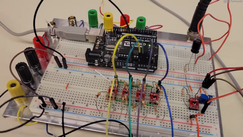
Canadian electronics geek and nascent YouTuber [Technoyaki] wanted to measure 20 volt signals on his Arduino. One might typically use a voltage divider to knock them down to the 5 volt range of the Arduino’s 10-bit A/Ds. But he isn’t one to take the conventional approach. Instead of using two resistors, [Technoyaki] decides to build an analog circuit out of sixteen resistors, four op amps and a separate 6 VDC supply.
What is a quantizer? In the usual sense, a quantizer transforms an analog signal (with an infinity of possible values) to a smaller (and finite) set of digital values. An A/D converter is a perfect example of a quantizer. [Technoyaki], stretching the definition slightly, and uses the term to describe his circuit, which is basically a voltage slicer. It breaks up the 20 V signal into four separate 5 V bands. Of course, one could almost accomplish this by just using an Arduino Due, which has a 12-bit A/D converter (almost, because it has a lower reference voltage of 3.3 V). But that wouldn’t be as much fun.
Why use all these extra components? Clearly, reducing parts count and circuit complexity was not one of [Technoyaki]’s goals. As he describes it, the reason is to avoid the loss of A/D resolution inherent with the traditional voltage divider. As a matter of semantics, we’d like to point out that no bits of resolution are lost when using a divider — it’s more accurate to say that you gain bits of resolution when using a circuit like the quantizer. And not surprising for precision analog circuitry, [Technoyaki] notes that there are yet a few issues yet to be solved. Even if this circuit ultimately proves impractical, it’s a neat concept to explore. Check out the video below the break, where he does a great job explaining the design and his experiments.
Even though this isn’t quite a cut-and-paste circuit solution at present, it does show another way to handle large signals and pick up some bits of resolution at the same time. We wrote before about similar methods for doubling the A/D resolution of the Arduino. Let us know if you have any techniques for measuring higher voltages and/or increasing the resolution of your A/D converters.


Resolution and accuracy are not the same. You claim to use 5% resistors to make “differential” amplifiers for the front end, but gain accurate diff amps need something like 0.1% or better resistor “matching” and that will then get a gain accuracy of no better than (meaning >) twice that or 0.2%. And that’s for only ONE stage. Since these stages are in parallel, the combined peak error would be about 4 times that or 0.8%. Assuming a 328’s 10bit ADC step size is accurate to 10 bits (which it isn’t), then that gives you a resolution of just under 0.1 (ideally, 1/1024). Since you use for 328 analog inputs to implement this, then you need to include the input-to-input gain and offset errors in your total calculation (and trust me, it ain’t easy), along with the errors of the input divider. While the error of each divider is bounded, their combined effect and be more significantly be degrading, especially when doing AC signal analysis since a super important quality factor called monotonicity kicks is, especially if you try to “measure” those AC signals with something like DFT/FFTs or other DSP techniques. And this analysis ignores the problem with phasing error between inputs, also critical for many DSP applications.
Frankly. it would be better to just go to a simple ARM micro with 12 bit ADCs if you really need that resolution (and some, like Seeed Studio Xiao are cheaper than many Uno clones at $5.40.. Of course, you still need to scale the signal’s dynamics to be compatible with the micro’s ADC with (yes) a two resistor divider (with some padding for caution!), but this only affects the gain accuracy (as an additional tolerance on the “typical” ADC step size) and has no (DC) offset error. Note that the input divider’s stray capacitance and inductance can affect AC gain over frequency.
I haven’t gone into much detail here, which is left as an exercise for you and others. I mainly wanted to point out missteps that can be the difference between a product that works to one doomed to fail.
Get a good DSP book (many are free and often available from manufacturers like TI, Microchip, Analog Devices, etc.) and really look closely at the manufacturer ADC data sheets for application guidance. And good luck on your journey, It’s clear, you have much farther to go.
Being correct doesn’t preclude you from being wrong.
Great video. Cool hack. Concise review of GoT S8E6.
Seriously, what does that even mean? Is this a philosophical Schrödinger’s cat thing, where something is the superposition of two states? It don’t work that way.
Spot on with all the performance problems. It is why higher bit count ADCs exist. It’s a fun approach though.
yeh, resistor tolerances are going to make this pointless. Better bet to sample faster and hope averages works in your favor
Sample faster with dither and average. What is best, noise with an average value of 1/2 LSB?
All that work, and he’s still using the five volt supply for the ADC reference? Not going to do the numbers, but I suspect he’s winding up with less accuracy than if he just divided the input by 20 and calibrated the Arduino’s internal reference.
Please correct me if I’m wrong, but the idea of “no voltage divider” is simply untrue. If you take a look at the schematic at 7:41 in the video, you’ll notice the telltale signs of a voltage divider on every non-inverting input of the op-amps.
I understand that the signal is sliced into 4 ranges which are then sampled individually. However, the input voltage still has to be scaled to the input range of whatever analog input stage components you are using. And, scaling can only by done with a voltage divider – whether it be resistors or a switched-capacitor setup.
An op-amp circuit at 7:41 in a video? What are the odds. I wonder if he did that on purpose as an Easter Egg.
I’m not clear on this circuit. It looks four followers. Two with unity gain, one with gain of 2 and one with gain of 3. They are following the voltage of the dividers.
The circuit is copnfusing because it says it measures a 20V range and shows a symbol with 20V. But it actually measures a 40V range and later in the video he shows how it did not measure an expected 36V signal at one point.
So, the first divider cuts the input in half (to 20V range) and the OA will ceiling at 5V. The second OA does the same but with 5V subtracted and when not floored or over-range it gives the 5V to 10V portion of a signal. Then the third OA has a divider to get 1/3 of the signal and a gain of two on the 5Vref to subtract 10V from 2(1/3) of 40? Brain not work. Need hamburger!
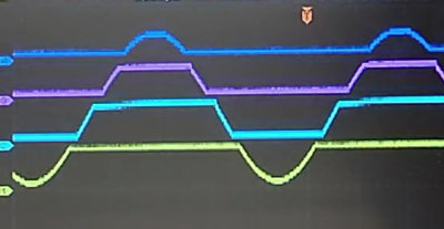
OK, I can appreciate the work that went into this but it is very screwed up. First, he is using an 18V amplitude which is 36V peak-to-peak and apparently using the negative rail of the signal generator as ground so that he can use a single sided op-amps and ADCs. Second, the resistor dividers on the non-inverting inputs all include a division by 2 from resistor values plus gain. This is why the op-amps “see” a 20V signal. I believe the 4 dividers should be R/R, R/R, 3R/R, and 5R/R. That is for a max 40V peak to peak signal and the 5V references as shown. This explains why the 4 traces do not match up well in the photos – the offsets are not correct. It doesn’t explain why the graph of the Arduino output after processing is so monotonic without gaps. I can not see how they come from the same source.
It is a great video to explain quantizer. Build it to understand how does a quantizer works. Check also the problems of this technology. Never use the components for a real measurement. You increase the resolution by two bits but you lost a lot of accuracy. The problem are:
You need high accuracy resistors, should be 0.01%, use precision OVs and use an accuracy 5V reference.
If you like to measure 0..20 V with the internal ADC, it is a better solution to use a OPV to get a high impedance of the analog input and 4:1 divider.
Say it again. It is a great video, but the wrong application. A helpfully application for a one channel of this quantizer would be : measure 12V. In a range from 10….14V with 10 bits.
If you like to learn more about quantizer problems, build the system as shown and look to the results on the ‘band edges’. 4.9 to 5.1 Vols, 9.9 to 10.1 volts and 14.9 to 15.1 volts.
Have fun.
So this is adding two bits at the MSB side of the ADC’s resolution while taking away an unknown number of bits at the LSB side due to some undefined noise characteristic.
It seems to me that a voltage divider would…
Still and nonetheless: exploring unconventional avenues is the hacker’s soul, so kudos :-)
Well, he is using 4 adc channels of arduino, which is in fact just one channel and multiplexer, so he never measures all of them in the same time, so yo have any valid results he must sample 8 times faster than max frequency of sig al and still it would add error due to sampling every channel at different time (unless he add hold and sample circuit)
well, conceivably you could calibrate out a lot of errors, from both design and component values, by using a linear ramp and fitting. that might make it harder to put actual values to the resolution achieved, but it would work.
i bet someone learned a thing or two doing this, and thats a cool thing right there.
Voltage divider for the range + oversampling can get you the extra 2-bit resolution without extra parts, gain/offset/common mode errors.
There’s a lot of references of using oversampling to gain resolution. But resolution is not accuracy (if confused, look it up). On average (and I use that word cautiously), the arithmetic mean of 4 measurements will has a theoretical limit of adding 2 bits of resolution. But to use oversampling to achieve BOTH increased resolution and accuracy (important if you want to claim that 4x oversampling adds 2 bits to the ADC), then that all “depends” on the underlying noise AND ADC linearity. If the ADC is VERY linear, and its noise is Gaussian (i.e. zero mean with “normal” curve) whose amplitude is just greater than 1 LSB, then it’s “possible” to get more resolution AND accuracy. Of course, it you are trying to sample AC signals and do DSP stuff on it, then that REALLY complicates everything. In the article’s associated video, the author show AC waveforms of “live” data, some with nasty glitches. Another comment pointed out that the windowed approach introduces other anomalies, but didn’t state their main issue, and that’s linearity AND monotonicity, especially important for AC analysis. If you don’t care about “jargon” and/or technical clarity, then just ignore my comments and continue to do whatever you “feel” is right.
Just curious is you know the difference between a “hack” and a professional solution.
Because I’m sure this is still Hackaday and not Professionaladay.
It “sounds” like you’re saying hackers don’t want to make good stuff, right? Well, I’ve been hacking since 1972, and my stuff keeps getting better because I care.
If you want to talk shop… Note I did use resolution, not accuracy. So you don’t score any points there.
Accuracy is only after you calibrate your ADC against a know reference that can be traceable to a standard. 5% resistors, gain offset errors and 5V from a regulator doesn’t get you that.
You can correct for non-linearity etc by doing a linear regression etc. to get accurate result. It should be part of tyhe calibration.
Like “true aliasing”, nonlinearity cannot be “undone” even with “regression analysis”, since the information is lost forever. It’s the old dilemma we learned in high school when we were taught the difference between “relations” and “functions” (see https://byjus.com/maths/difference-between-relation-and-function/). Functions have an UNAMBIGUOUS, one-to-one relationship whereas relations can have a one-to-many or many-to-one relationship which eliminates the ability to uniquely determine “where it came from”. It’s one of the banes of higher math. When doing AC analysis (and many other types of analyses) nonlinearity introduces non-recoverable distortion (i.e. ambiguity). Some AC analysis methods, like the DFT/FFT can handle Gaussian noise because the Fourier transform of Gaussian noise is itself Gaussian noise. If an ADC has some jiggling present in its conversion process, then it can still be used for AC analysis if the conversion process is monotonic — this means that every higher analog input level results in an equal OR higher output code (since it’s a function) and NEVER a lower code (because THEN it’s no longer a “function”, but a “relation”).
And accuracy does not necessary require an “accurate reference” voltage (or other unit), since it can have high “relative” accuracy. And without high relative accuracy, calibrating to reference is a waste of time. For example, due to things like fading (changes in amplitude), AC analysis of communications channels require accurate RELATIVE amplitude comparisons to determine the signal’s identity. Some communications require accurate phasing comparison, that CANNOT be “fixed” with a gain adjustment, absolute or otherwise. Phase accuracy requires monotonicity (i.e. linearity) and nonlinearities can corrupt the phase data irretrievably, garbling the data often more than even error-correction can compensate for.
My point is that “it’s just not that simple” no matter how much you protest about something being “over-technical”.
BTW if you don’t calibrate the ADC, you don’t have accuracy. Might want to look that up before laying down a wall of text.
The commenter above is trying to explain why you can’t calibrate out the error and achieve the accuracy of the additional bits that are provided. The information is lost and can’t be regained through linear regression or even mysticism. You can get additional resolution by an almost infinite number of methods, but the question is does that resolution mean anything?
A hack implies a shortcut, or a novel or interesting way to get to achieve a result. It can be impractical but fun, just like a Rube Goldberg setup is fun. But the assumption is that it does “Work”.
I would suggest reading and understanding what the commenter above is saying, because he is correct. Those additional bits you get by this method don’t really mean anything, because they will not accurately represent the input signal no matter how you attempt to calibrate it, because the information is lost.
I was pretty confused by this project write-up before I realized I was getting two different definitions of “quantizer” mixed up. I’ve recently been doing a lot of work with modular synthesizers, where a quantizer is a device that takes an input voltage and outputs a related voltage, but adjusted to particular values. So if your synthesizer works on the volt-per-octave standard, and your quantizer is set to output the 12 equally-tempered tone values in each volt, putting in 3.01 volts will give you an output of 3.0v; if your input is closer to 3.08v, you’ll get out 3.0833…v (3 1/12); the difference between the two output voltages feeding an oscillator (and thus generating tones) is a semitone, or the difference between C and C#.
Presumably a musical quantizer is called that because the original, analog units used a quantizer (in the more technical sense) to do some of their mapping, though were I to implement one I’d probably jump to window comparators, or just go with a micro and matching ADCs and DACs. I know there are both sorts on the market.
HaD you should remove this until it is fixed.
Hi, since the arduino has 6 analog in inputs, insted of reading 20vdc maximum, we can split 3 analog pins to postive tension and the other 3 to negative tension. How to view negative tensions with the arduino only reading positive (0-5v) ? Well, invert the negative tension with a op amp and arduino will accept that, then at software level invert it again showing the wave below 0v. Then we can view in the screen waves from -15v to +15v.