Photo of a prototyping breadboard with an Arduino, whose analog inputs are connected to an array of four small op-amp circuits which perform the voltage slicing function of the Quantizer circuit described in this article.

Arduino Measures 20V Signals Using Quantizer

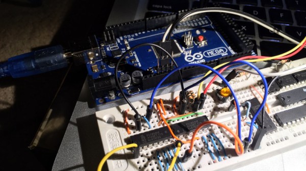
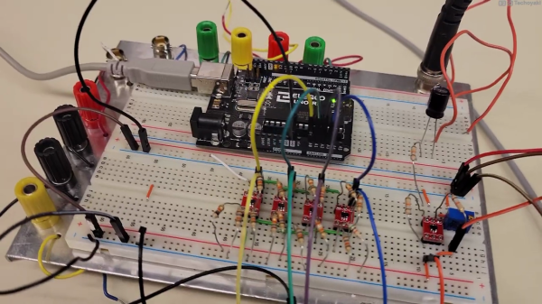
Canadian electronics geek and nascent YouTuber [Technoyaki] wanted to measure 20 volt signals on his Arduino. One might typically use a voltage divider to knock them down to the 5 volt range of the Arduino’s 10-bit A/Ds. But he isn’t one to take the conventional approach. Instead of using two resistors, [Technoyaki] decides to build an analog circuit out of sixteen resistors, four op amps and a separate 6 VDC supply.

Oscilloscope photo showing the output signals from each of the quantizer's four op amps. They are positioned staggered on the screen so that you can see the original sinusoidal signal clearly.

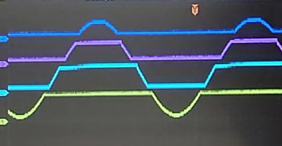
What is a quantizer? In the usual sense, a quantizer transforms an analog signal (with an infinity of possible values) to a smaller (and finite) set of digital values. An A/D converter is a perfect example of a quantizer. [Technoyaki], stretching the definition slightly, and uses the term to describe his circuit, which is basically a voltage slicer. It breaks up the 20 V signal into four separate 5 V bands. Of course, one could almost  accomplish this by just using an Arduino Due, which has a 12-bit A/D converter (almost, because it has a lower reference voltage of 3.3 V). But that wouldn’t be as much fun.

Why use all these extra components? Clearly, reducing parts count and circuit complexity was not one of [Technoyaki]’s goals. As he describes it, the reason is to avoid the loss of A/D resolution inherent with the traditional voltage divider. As a matter of semantics, we’d like to point out that no bits of resolution are lost when using a divider — it’s more accurate to say that you gain bits of resolution when using a circuit like the quantizer.  And not surprising for precision analog circuitry, [Technoyaki] notes that there are yet a few issues yet to be solved. Even if this circuit ultimately proves impractical, it’s a neat concept to explore. Check out the video below the break, where he does a great job explaining the design and his experiments.

Even though this isn’t quite a cut-and-paste circuit solution at present, it does show another way to handle large signals and pick up some bits of resolution at the same time. We wrote before about similar methods for doubling the A/D resolution of the Arduino. Let us know if you have any techniques for measuring higher voltages and/or increasing the resolution of your A/D converters.

Continue reading “Arduino Measures 20V Signals Using Quantizer”

High Precision Analog IO With Digital Pins

Reading the temperature of your environment is pretty easy right? A quick search suggests the utterly ubiquitous DHT11, which speaks a well documented protocol and has libraries for every conceivable microcontroller and platform. Plug that into your Arduino and boom, temperature (and humidity!) readings. But the simple solution doesn’t hit every need, sometimes things need to get more esoteric.

The technique summarized by an image from Microchip Appnote AN685

For years we’ve been watching [Edward]’s heroic efforts to build accessible underwater sensing hardware. When we last heard from him he was working on improving the accuracy of his Arduino’s measurements of the humble NTC thermistor. Now the goal is the same but he has an even more surprising plan, throw the ADC out entirely and sample an analog thermistor using digital IO. It’s actually a pretty simple trick based on an intuitive observation, that microcontrollers are better at measuring time than voltage. 

The basic circuit

The circuit has a minimum of four components: a reference resistor, the thermistor, and a small capacitor with discharge resistor. To sense you configure a timer to count, and an edge interrupt to capture the value in the timer when its input toggles. One sensing cycle consists of discharging the cap through the discharge resistor, enabling the timer and interrupt, then charging it through the value to measure. The value captured from the timer will be correlated to how long it took the cap to charge above the logic-high threshold when the interrupt triggers. By comparing the time to charge through the reference against the time to charge through the thermistor you can calculate their relative resistance. And by performing a few calibration cycles at different temperatures ([Edward] suggests at least 10 degrees apart) you can anchor the measurement system to real temperature.

For all the gory details, including tips for how to save every last joule of energy, check out [Edward]’s post and the Microchip appnote AN685 he references. Besides this series [Edward]’s Cave Pearl Project has already yielded an impressive number of Hackday posts. For more great hardware writeups check out a general hardware build for a single sensing node, or the “temperature sensor” [Edward] made with no external parts at all!

An Epic Tale Of Thermistors: Tricks For Much Better Temperature Sensing

For years [Edward] has been building professional grade underwater sensing nodes at prices approachable for an interested individual without a government grant. An important component of these is temperature, and he has been on a quest to get the highest accuracy temperature readings from whatever parts hit that sweet optimum between cost and complexity. First there were traditional temperature sensor ICs, but after deploying numerous nodes [Edward] was running into the limit of their accuracy. Could he use clever code and circuitry to get better results? The short answer is yes, but the long answer is a many part series of posts starting in 2016 detailing [Edward]’s exploration to get there.

Orange is 12 bits, red is 24

The first step is a thermistor, a conceptually simple device: resistance varies with temperature (seriously, how much more simple can a sensor get?). You can measure them by tapping the center of a voltage divider the same way you’d measure any other resistance, but [Edward] had discarded this idea because the naive approach combined with his Arduino’s 10 bit ADC yielded resolution too poor to be worthwhile for his needs. But by using the right analog reference voltage and adjusting the voltage divider he could get a 20x improvement in resolution, down to 0.05°C in the relevant temperature range. This and more is the subject of the first post.

What comes next? Oversampling. Apparently fueled by a project featured on Hackaday back in 2015 [Edward] embarked on a journey to applying it to his thermistor problem. To quote [Edward] directly, to get “n extra bits of resolution, you need to read the ADC four to the power of n times”. Three bits gives about an order of magnitude better resolution. This effectively lets you resolve signals smaller than a single sample but only if there is some jitter in the signal you’re measuring. Reading the same analog line with no perturbation gives no benefit. The rest of the post deals with the process of artificially perturbing the signal, which turns out to be significantly complex, but the result is roughly 16 bit accuracy from a 10 bit ADC!

What’s the upside? High quality sensor readings from a few passives and a cheap Arduino. If that’s your jam check out this excellent series when designing your next sensing project!

Double The Resolution, From An Arduino ADC

Analog-to-digital converters, or ADCs, are somewhat monolithic devices for most users, a black box that you ask nicely for the value on its input, and receive a number in return. For most readers, they will be built into whatever microcontroller is their platform of choice, and their resolution will be immutable, set by whatever circuitry is included upon the die. There are a few tricks that can be employed to get a bit more from a stock ADC though, and [Neris] has taken a look at a couple of them.

The first circuit doubles the resolution of an ADC, in this case, that of the Atmel chip in an Arduino, by converting its output from an integer to a signed integer. It performs this task with a precision rectifier, rectifying around a zero-crossing point half-way through the range of the analog value to be read and supplying a sign bit to the Arduino. The Arduino measures the rectified analog value to an integer, and applies the appropriate sign from the supplied bit value.

The second circuit takes a variation on the same technique but with two ADCs instead of one. A pair of PIC chips are used with their voltage references stacked one above the other, by taking both readings in combination a result with double the resolution can be derived.

You might ask why bother with these techniques. After all, there are plenty of higher-resolution ADCs on the market. But they’re useful techniques to know, should you ever need to extract the proverbial quart from a pint pot.

If ADCs are a mystery to you, you’re in luck. [Bil Herd] gave us a comprehensive introduction to the subject.