The Retro Shield, an Arduino Proto Shield for making many different circuits.

Retro Shield Replaces Springs With Jumpers, Includes Blinkenlights!

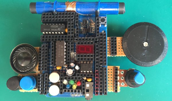
Is it an AM radio? Yes. It is a 555 LED flashing circuit? Yep. How about a hex counter with a 7 segment display? That too. Five different colored LED’s to satisfy your need for blinkenlights? Even that! What is this magical contraption? Is it one of those old school 30-in-1 or 50-in-1 “Science Fair” kits with the jumper wires and the springs? Almost!

When [grandalf]’s friend showed them a project where a 555 timer was installed on an Arduino shield, they realized two things: This whole “could have done that with a 555 timer” meme is a lot of fun, and “I’ve got an old 556 chip, I wonder if I can build one?” The answer is yes, and so much more.

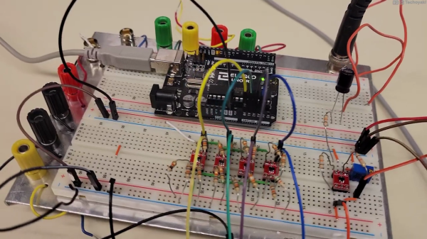
Starting with the 556 timer, and inspired by the old spring-and-jumper kits of the past, [grandalf]’s “556 on a Proto Shield” project evolved into a creation they call the Retro Shield. Snowballing like so many hacker projects, it now includes several built in circuits and components. Breadboard jumpers are used to connect components through strategically placed pin headers, of which there are quite a few!

To make it all fit, some parts were substituted with more compact pieces such as an LM386 instead of an LM380.  The AM radio portion is supplied by an all-in-one radio chip, the ZN414. With the scope creep picking up steam, [grandalf] eventually added so called sidecars- bits of board that contain controls and a speaker hanging off the side of the Proto Shield.

It is not mentioned if the Retro Shield integrates with the Arduino or not. All the same, the Retro Shield has been used to pick up local AM stations, blink LED’s and amplify audio with the LM386. Like [grandalf] we’re sure that the Retro Shield can be used for much more. We hope that [grandalf] expands on the concept and inspires future hackers to answer the question “I wonder what happens if I try this.” 

If you haven’t set eyes on one of the all-in-one kits, check out this 200-in-1 kit teardown and review. And of course, if you have your own hacked up projects to share, be sure to let us know through the Tip Line!

Smooth Servo Motion For Lifelike Animatronics

Building an animatronic robot is one thing, but animating it in a lifelike fashion is a completely different challenge. Hobby servos are cheap and popular for animatronics, but just letting it move at max speed isn’t particularly lifelike. In the video after the break, [James Bruton] demonstrates how to achieve natural motion with a simple animatronic head and a few extra lines of code.

Very little natural body movement happens at a constant speed, it’s always accelerating or decelerating. When we move our heads to look at something around us, our neck muscles accelerate our head sharply in the chosen direction and then slows down gradually as it reaches its endpoint. To do this in Arduino/C code, a new intermediate position for the servo is specified for each main loop until it reaches the final position. The intermediate value is the sum of 95% of the current position, and 5% of the target position. This gives the effect of the natural motion described above. The ratios can be changed to suit the desired speed.

The delay function is usually one of the first timing mechanisms that new Arduino programmers learn about, but it’s not suited for this application, especially when you’re controlling multiple servos simultaneously. Instead, the millis function is used to keep track of the system clock in the main loop, which fires the position update commands at the specified intervals. Adafruit wrote an excellent tutorial on this method of multitasking, which [James] based his code on. Of course, this should be old news to anyone who has been doing embedded programming for a while, but it’s an excellent introduction for newcomers.

Like most of [James]’s projects, all the code and CAD files are open source and available on GitHub. His projects make regular appearances here on Hackaday, like his mono-wheel balancing robot and mechanically multiplexed flip-dot display.

Continue reading “Smooth Servo Motion For Lifelike Animatronics”

An Earthquake Display To Keep You Abreast Of Rumblings Worldwide

The Internet has brought us the ability to share data all over the globe, and nearly instantaneously at that. It’s revolutionized the sharing of science across the world, and taking advantage of this global data network is this earthquake display from [AndyGadget].

The build relies on an ESP32 fitted with an ILI9486 TFT display. The screen is in color and has a nice 480×320 resolution. This enables it to display a reasonably legible world map using the Web Mercator projection to fit the rectangular screen. The microcontroller then pulls in information from Seismic Portal, a site that aggregates data from seismographs and other sensors scattered all over the world.  Data from the site is pulled into the device live and overlaid on the world map, allowing the viewer to see the location of any current earthquakes at a glance.

It’s a great project, and one that we reckon would make a great addition to any university geology department. If it’s sparked an interest, consider diving deeper into the world of seismic analysis and data yourself!

Photo of a prototyping breadboard with an Arduino, whose analog inputs are connected to an array of four small op-amp circuits which perform the voltage slicing function of the Quantizer circuit described in this article.

Arduino Measures 20V Signals Using Quantizer

Canadian electronics geek and nascent YouTuber [Technoyaki] wanted to measure 20 volt signals on his Arduino. One might typically use a voltage divider to knock them down to the 5 volt range of the Arduino’s 10-bit A/Ds. But he isn’t one to take the conventional approach. Instead of using two resistors, [Technoyaki] decides to build an analog circuit out of sixteen resistors, four op amps and a separate 6 VDC supply.

Oscilloscope photo showing the output signals from each of the quantizer's four op amps. They are positioned staggered on the screen so that you can see the original sinusoidal signal clearly.

What is a quantizer? In the usual sense, a quantizer transforms an analog signal (with an infinity of possible values) to a smaller (and finite) set of digital values. An A/D converter is a perfect example of a quantizer. [Technoyaki], stretching the definition slightly, and uses the term to describe his circuit, which is basically a voltage slicer. It breaks up the 20 V signal into four separate 5 V bands. Of course, one could almost  accomplish this by just using an Arduino Due, which has a 12-bit A/D converter (almost, because it has a lower reference voltage of 3.3 V). But that wouldn’t be as much fun.

Why use all these extra components? Clearly, reducing parts count and circuit complexity was not one of [Technoyaki]’s goals. As he describes it, the reason is to avoid the loss of A/D resolution inherent with the traditional voltage divider. As a matter of semantics, we’d like to point out that no bits of resolution are lost when using a divider — it’s more accurate to say that you gain bits of resolution when using a circuit like the quantizer.  And not surprising for precision analog circuitry, [Technoyaki] notes that there are yet a few issues yet to be solved. Even if this circuit ultimately proves impractical, it’s a neat concept to explore. Check out the video below the break, where he does a great job explaining the design and his experiments.

Even though this isn’t quite a cut-and-paste circuit solution at present, it does show another way to handle large signals and pick up some bits of resolution at the same time. We wrote before about similar methods for doubling the A/D resolution of the Arduino. Let us know if you have any techniques for measuring higher voltages and/or increasing the resolution of your A/D converters.

Continue reading “Arduino Measures 20V Signals Using Quantizer”

Wearable Scope Lets Your Fingers Do The Probing

For frantic hacking sessions where seconds count, this forearm mounted oscilloscope with fingertip probes built by [aniketdhole] might be just what you need. Well, maybe. It’s not immediately clear why you might want to wear an oscilloscope on your arm, and sticking your fingers inside of powered up electronic devices sounds specifically like something your mother probably told you not to do, but here it is anyway.

The scope consists of an nRF5340 evaluation board in a 3D printed mount, with an SPI-connected Adafruit 2.8″ TFT display on top. With a pair of wires run from the board’s ADC and ground pins, [aniketdhole] just needed a bit of code to glue it all together and show some basic signal visualizations on the display. It’s been tested against PWM signals generated by an Arduino and some potentiometer controlled voltages, but anything much wilder than that is probably a bit too much to ask for from this rig in its current configuration.

In the future, [aniketdhole] wants to add some step-down circuity so you can probe higher voltages than the nRF5340 can handle normally, as well as a shunt to allow current measurement. Once the hardware is in place, the next order of business will be an improved touch-capable user interface that lets the user adjust settings and switch between functions.

Even if you’re not sold on the idea of an arm-mounted oscilloscope, this is still an interesting platform for general wearable experimentation. Throw enough sensors into it, and we’re sure there’s more than a few hackers who wouldn’t mind strapping one of these on.

Troubleshooting: A Method For Solving Problems The Right Way

We’ve all experienced that magic moment when, after countless frustrating hours of experimentation and racking your brain, the object of our attention starts working. The 3D printer finally produces good output. The hacked up laptop finally boots. The car engine finally purrs. The question is, do we know why it started working?

This is more important than you might think. Knowing the answer lets you confirm that the core problem was solved, otherwise you may have just fixed a symptom. And lack of understanding means fixing one problem may just create another.

The solution is to adopt a methodical troubleshooting method. We’re talking about a structured problem solving technique that when used properly can help us solve a problem at its core without leaving any loose ends. Such methodology will also leave you knowing why any solution did or didn’t work in the end, and will give you reproducible results.

Continue reading “Troubleshooting: A Method For Solving Problems The Right Way”

Hackaday Podcast 134: Hackers Camping, Metal Detecting, 360° Hearing, And Pocket Computing

Hackaday editors Elliot Williams and Mike Szczys are joined by contributing editor Jenny List to talk about her adventure at Born Hack last week. We also discuss the many capacitor values that go into regen receivers, the quest for a Raspberry Pi handheld that includes a slide-out keyboard, and how capacitive touch might make mice (mouses?) and touchpads better. There’s a deep dive into 3D printer bed leveling, a junk-box metal detector build, and an ambisonic microphone which can listen any-which-way.

Take a look at the links below if you want to follow along, and as always, tell us what you think about this episode in the comments!

Direct download (60 MB or so.)

Continue reading “Hackaday Podcast 134: Hackers Camping, Metal Detecting, 360° Hearing, And Pocket Computing”