What does “breadboard-friendly” mean to you? It’s become a game of minimum viability. Sure, it fits in the breadboard, but are there any accessible tie points left for wires and components? What good is a development board if you can’t easily prototype with it?
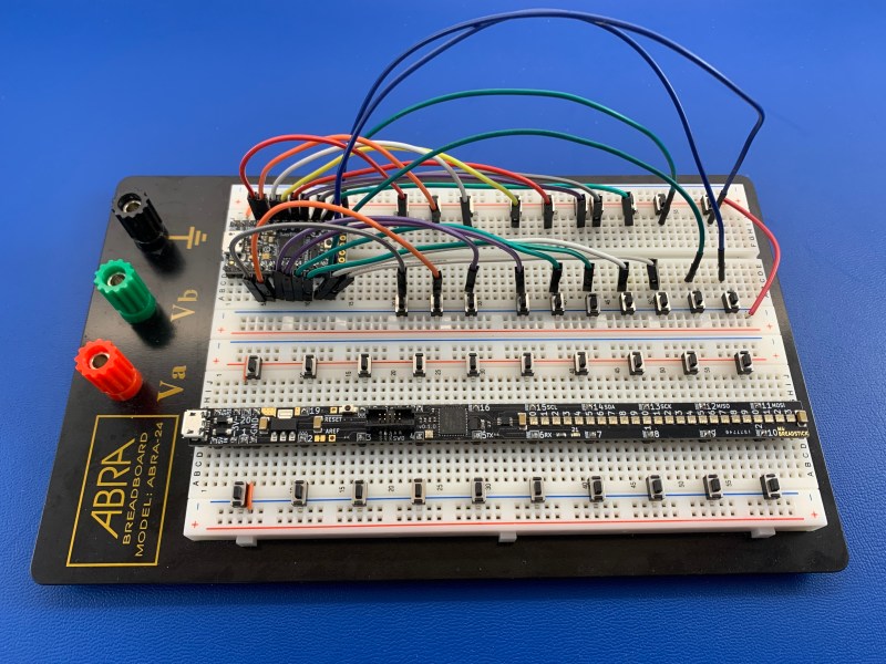
A few years ago, [Michael Rangen] set out to change all of that by creating a long and skinny development board that spaces out the I/O pins and simplifies wiring, making every circuit beautiful and easier to take in visually. The current version is an adaptation of Adafruit’s ItsyBitsy M4 Express. It has 20 I/O pins, all spread out along the length and numbered around the horn like an IC. [Michael] dipped this breadstick in 24 tiny RGB LEDs, all of which are on a dedicated com bus.
We think this is a great idea that will definitely make microcontrollers more hackable. This type of layout would make checking students’ work a breeze, and you can make tidy prototypes with it yourself after class. Today the board runs CircuitPython, and it will be able to run Arduino in the future.
![]()


For this purpose, I’ve used my design skills to make a _vertical_ aligned demo board for myself…
https://www.instructables.com/Breadboard-Compatible-PIC18F25J50-Demoboard/
Ohhh I may need to steal this one. I use ATMega328p a lot and the standard chip can be a bit crowded. Time to fire up Eagle CAD and make it extra long and skinny Nano variant
This is clearly one of those “I didn’t know I needed it until I saw it” hacks. I need one. There’s a Crowd Supply project pending for these lovelies at: https://www.crowdsupply.com/breadstick-innovations/m4-breadstick.
breadboarding seems antiquated these days, in that it never really kept up with technology. it made perfect sense back when everything came in dip packages and everything was point to point. breadboard friendly dev boards are kind of a bridge, but i think the breadboard itself needs to move forward. would be better if they had integrated crossbar matrices and high speed capable busses. have each short row terminated at a cross bar with an array of dip switches that can tie that into the adjacent bus. another dip switch in the spine can connect each half of a cross bar to the other. thus you can route power or i2c to any crossbar without laying a single jumper.
you can take things further by making them lego compatible by attaching them to a lego baseplate (or a lego robot). spring terminals in the side can make connections between boards. these would tie into each crossbar on the sides and busses at the ends, all via another dip switch. the terminals can be genderless so you can rotate them into any orientation, say routing a bus into a cross bar if connected at 90 degree angles. you can also make crossbars and busses as separate modules and arrange them as needed.
Nice idea. Have attempted to make breadboard pluggable modules but all a bit clunky as used through hole components. All for audio design. Perhaps it needs revisiting with some surface mount goodness.
Getting rid of some of the power wires, decoupling caps and clutter would be nice for any breadboard project.
There is always the breadshield. I have a few of them and use them all the time for prototyping. I actually found it here on hackaday!
https://www.crowdsupply.com/loser/breadshield
i guess i don’t see the point. i don’t see a lot of in-between room between projects where i’m only using a few pins (a breadboard can be pretty handy) and projects where i’m using so many wires that breadboarding seems implausible and i’d rather wirewrap. so long as there’s a SIP pin header i always at least have that choice.
really, i mostly use the breadboard for analog circuits that i’m not very confident in…especially if i’m not sure what values i might want for R or C. a lot of analog circuits, i still don’t know if it’ll work at all, or i have to tune it in over iterations. but digital circuits, i typically know how it’s gonna go and i skip the breadboarding step. semi-permanent connections are fine if i’m not gonna be using guess-and-check just to find basic component paremeters. i might have 2-5 wires coming off an stm32 board by jumper wire and going to a breadboarded filter/amplifier sort of thing…
They are breadboard shields for arduino.
IMO that name is genius.
There’s a successor to this project, check it out here!
https://www.crowdsupply.com/breadstick-innovations/raspberry-breadstick