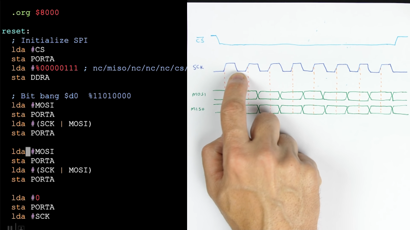
With the prevalence of libraries, it has never been easier to communicate with hundreds of different sensors, displays, and submodules. But what is really happening when you type SPI.begin() into the Arduino IDE? In his most recent video, [Ben Eater] explores the Serial Peripheral Interface (SPI) and how it really works.
Most Hackaday readers probably know [Ben] from his breadboard-based computers, such as the 6502 build we featured in 2019. Since then he has been hard at work, adding new and interesting additions to his breadboard computer, as well as diving into different communication protocols to better understand and implement them. For this video, [Ben] set the goal of connecting the BME280, a common pressure, temperature, and humidity sensor with an SPI interface, to his breadboard 6502 computer. Along the way, [Ben] discusses how exactly SPI works, and why there is so much conflicting nomenclature and operations when looking at different SPI devices.
If breadboard computers aren’t your thing, there are tons of other uses for the BME280, such as helping to modernize a Casio F-91W.


SPI rules. i2c drools.
It also needs a bunch of connections/pins/wires.
If by a bunch you mean one more bus line and one CS per chip. I’d much rather do that than deal with bus lock and multiplexing if you have multiple chips with the same address. The only real place I’d rather deal with I2C is if I was designing for an extremely small footprint (wearables, etc) and the extra pins would necessitate going up a package size.
For one project I needed 16 of the same sensor that only came in I2C. Luckily, they had reprogrammable addresses, but I still needed a multiplexer (I chose an SPI unit) to assign those addresses (mostly for initial commissioning, though I incorporated a check that would run the routine should a sensor forget its address, never saw the warning LED for that come on though). I’d have much preferred to just go up to a QFN30 or 40 for the CS pins and forget about the multiplexer and address assignation routine. Higher baud and less communication overhead would have been convenient, too.
I actually prefer I2C for anything that doesn’t need lots of bandwidth. SPI requires so many pins: MISO, MOSI, CLK and CS, whereas I2C only requires two. Then, in addition to this, most SPI-devices also have a separate RESET-pin as well, whereas with I2C, you can issue a bus-reset to reset all the sensors/devices connected to it, further reducing the number of pins used.
Yes, faster is better in a purely technical sense and so SPI is better there, but for *practicality* in terms of hooking up I2C-devices via jumper-wires or for designing a quick PCB, I2C wins, IMHO.
SPI doesn’t always require all those pins. There are read-only or write-only devices that do not need both data pins. You can multiplex csn pins. Reset for SPI could also be bus wide. And many I2C devices lack a reset pin. I2c has so many potential issues other than bandwidth and it being non-deterministic (clockstretching). The bus can lock up after a glitch for instance. It is more difficult to isolate I2C. Bus capacitance etc.
Agreed on all points. But I2C requires only two data lines and is multidrop. It can be a PITA, but it also has its place. I do prefer working with SPI though!
“SPI doesn’t always require all those pins. There are read-only or write-only devices that do not need both data pins. ”
That’s because SPI isn’t a standard. There’s literally no requirement on anything, because… there are no requirements. At all. None. Zero. Microcontroller SPI peripherals are in general flexible enough to handle just about any possible behavior of the target, but that’s just because designers aren’t dumb.
Saying “oh, there are simpler SPI devices, so the pin count isn’t an issue” is silly: there are I2C devices that are deterministic and have no lockup issues, either. SMBus devices are I2C devices, after all.
“And many I2C devices lack a reset pin. I2c has so many potential issues other than bandwidth and it being non-deterministic (clockstretching). The bus can lock up after a glitch for instance.”
So? Glitches can eff up any poorly-designed device. SPI has no byte framing or acknowledgement requirement, so a clock glitch can lead to completely undefined behavior anyway. Clock stretching was totally a dumb idea in the I2C spec, absolutely, which is why now technically it’s an optional behavior to support for a master (and in the spec it should really be explicitly discouraged at this point).
I2C has a base specification, and so it’s absolutely possible to verify that a design will work. I2C compatible master, I2C compatible slave, check bus capacitance and pull-up resistor value. Done. With SPI it’s more of a Wild West issue, where you need to check everything yourself to see if it’ll work.
Part of the reason why SPI Flash is so nice is that it’s basically a specified version of SPI. You’ve got JEDEC-standardized commands, a relatively uniform standard, etc. It’d be really really nice if more microcontrollers had full “SPI Flash” interfaces rather than just SPI.
I don’t get your comment. As far as I know, there is no bus-wide reset for all devices connected to the SPI-bus. For I2C, there is. I am not talking about resetting the bus itself, but all the devices connected to it. That’s why many I2C-devices don’t have a reset-pin: they don’t need one!
They mean that you can just add a single extra line to the bus, wired to the !RESET input of every SPI chip/device on the bus, and use that to reset.
If you use your cs lines as address lines to be decoded at the device end then you could actually assign an address for !RESET and use that to fire off the reset.