When it comes to getting signals from an analog world into our computers, most of us don’t give much thought to how the hardware that does the job works. But as it turns out, there are a number of ways to skin the analog to digital conversion cat, and building your own homebrew successive approximation register ADC is a great way to dispel some of the mystery.
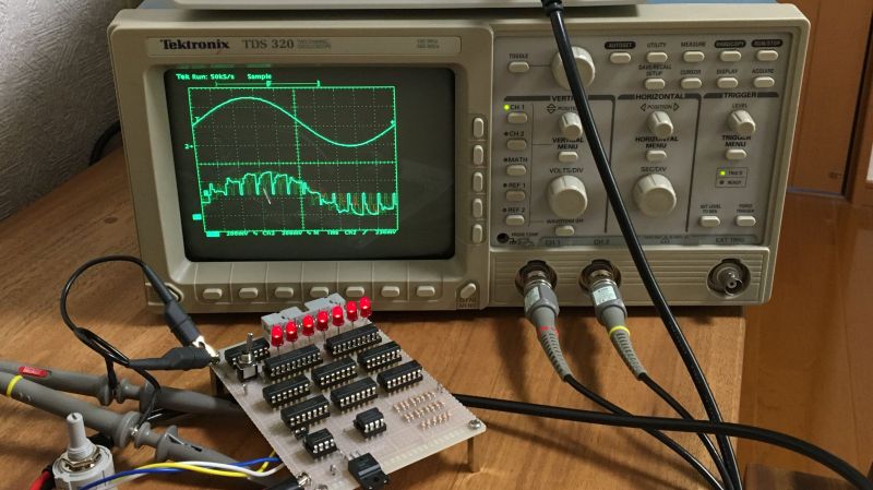
From his description of the project, it’s clear that [Mitsuru Yamada] wasn’t looking to build a practical ADC, but was more interested in what he could learn by rolling his own. A successive approximation register ADC works by quickly cycling through all possible voltage levels in its input range, eventually zeroing in on the voltage of the input signal at that moment and outputting its digital representation. The video below shows how the SAR ADC works visually, using an oscilloscope to show both the input voltage and the output of the internal R-2R DAC. The ADC has an input range of 0 V to 5 V and seven bits of resolution and uses nothing but commonly available 74xx series logic chips and a couple of easily sourced analogs for the sample-hold and comparator section. And as usual with one of his projects, the build quality and workmanship are impeccable.
We love these sorts of projects, which are undertaken simply for the joy of building something and learning how it works. For more of [Yamada-san]’s projects, check out his 6502-based RPN calculator, or the serial terminal that should have been.


I kind of understand what is happening in the video, but I will need to see schematic to understand it better.
I’m sure I have the chips and components to build this.
It will be an educational experience for me.
Thanks for doing this!
Thanks. I am the author of the article. I first built this and a ADC 42 years ago when I was 19 years old. I was very excited to experience the aliasing phenomenon caused by the sampling theorem while looking at the screen of the oscilloscope.
SAR’s are easy, ulitmately, it’s just a series of “higher or lower?” questions.
The ones I can never understand are the delta/sigma converters. Every once in a while I’ll stare at a data sheet long enough to finally get the gist it, then I’ll get up from the bench to get a cup of coffee, come right back…. aaannnd… it’s gone.
You probably won’t get it. The amount of numerical analysis and filter theory and Fourier stuff baked into a delta/sigma chip is insane. However, a project like this one but doing a complete discrete delta/sigma would be really great. Maybe controlled by an Arduino Nano. I guess it should really be the chopper-comparator and the rest is software. Hmmm there is one bit of feedback IIRC.
I have a fat textbook on design of these things. I was a bit disappointed that the author rolls developments into integrated hardware as he progresses. However, the basis of it is a lot more accessible now. The chop-the-input and sort it out later with noise shaping and filtering and other digital incantations is basically the same as in SDR receivers except not as I/Q complex numbers.
It’s a great project, hands-on designing and building to understand. It makes me ponder how ADC is achieved in two vintage computing devices I own, those being Woz’ ingenious simplicity of the 558 timer (software supported) ADC for reading the paddles in the Apple ][, contrasted with the complexity of a late 1960s 19″ heavy rack-mount DEC ADC unit for the PDP-8/9/11 chock-full of flip-chip boards of discrete components.
The Woz gizmo for paddles and joysticks charges a capacitor through the pot in the hand controller. The time it takes to charge is proportional to the resistance. Taking a little time to do it sounds like an accuracy problem and it it is. But not as bad as it might seem because the result is basically the average resistance during the charge interval.
I can’t remember if it charges then measure discharge time though a constant current sink (can be a single transistor and two resistors) for dual slope ADC which can be very high precision) or just runs the timer until a comparator on the cap says stop. Something like that anyway. Charging a cap this way gives an exponential curve. If you use just the beginning of the charging curve it is close to a straight line. Woz probably does that to speed things up.
I have a “Red Book” but didn’t look up the circuit and explanation. You can find a Red Book PDF online. Funny a quick search does not reveal anything on a such an iconic piece of hardware.
Thank you, I am the author of the article. My experience with this project 42 years ago is one of the reasons why I am still working in the electronics field. Advanced technology is evolving rapidly, but I believe that principles and fundamentals are important.
A SA ADC does not “cycle through all possible voltage levels”, it essentially does a binary search starting with the MSB. So a 7-bit SA ADC does seven comparisons, i.e. cycling through seven of the 128 possible voltage levels.