When [Nicole Express] got her hands on the logic board for the 1986 SNK arcade game Athena, she ran into a rather thorny problem: The board expected to be fed negative five volts! [Nicole]’s analysis of the problem and a brilliant solution are outlined in her well written blog post.
[Nicole]’s first task was to find out which devices need negative voltage. She found that the negative five volts was being fed through a capacitor to the ground pins on the Mitsubishi M151516L, an obscure 12 W audio amplifier. After finding the data sheet, she realized something strange: the amp didn’t call for negative voltage at all! A mystery was afoot.
To fully understand the problem, she considered a mid-1980’s arcade and its cacophony of sounds. How would a manufacturer make their arcade game stand out? By making it louder, obviously! And how did they make their game louder than the rest?
The answer lays in the requirement for negative five volts. The amplifier is still powered with a standard 12 V supply on its VCC pin. But with ground put at -5 V, the voltage potential is increased from 12 V to 17 V without overpowering the chip. The result is a louder game to draw more players and their fresh stacks of quarters.
How was [Nicole Express] to solve the problem? ATX PSU’s stopped providing -5 V after the ISA slot disappeared from PC’s, so that wouldn’t work. She could have purchased an expensive arcade style PSU, but that’s not her style. Instead, she employed a wonderful little hack: a charge pump circuit. A charge pump works by applying positive voltage to a capacitor. Then the capacitor is quickly disconnected from power, and the input and ground are flipped, an equal but negative voltage is found on its opposite plate. If this is done with a high enough frequency, a steady -5 V voltage can be had from a +5 V input. [Nicole Express] found a voltage inverter IC (ICL7660) made just for the purpose and put it to work.
The IC doesn’t supply enough power to get 12 W out of the amplifier, and so the resulting signal is fed into an external amplifier. Now [Nicole]’s arcade game has sound and she can play Athena from the original arcade board, 1986 style!
Arcades are few and far between these days, but that doesn’t mean you can’t introduce your young ones to the joys of dropping a quarter or two, or build a gorgeous oak Super Mario Bros cabinet complete with pixel art inlays. Do you have a favorite hack to share? Be sure let us know via the Tip Line!


A mistake here: “ATX PSU’s stopped providing negative voltage after the ISA slot disappeared from PC’s”
ATX PSUs have always, and to this day, provide negative 12V (used to this day for things like RS232 drivers on motherboards that have a COM port header (still relatively common)). It was negative 5V that was removed from ATX PSUs early on.
A very simply way of getting negative 5V from negative 12V, is a 20 cent 7905 regulator IC, provided the PSU can provide enough current (which an ATX PSU likely can’t on its negative 12V rail).
Something does not add up.
-5VDC isn’t going to go through a capacitor any more than 5VDC will go through a capacitor.
Even if it did, the part is rated to operate on 16V. From -5 to 12V is 17, so it would be operating outside its specications.
Additionally, it is rated to produce 12W when operated on its rated voltage.
I think there’s something else going on. You’d need a full schematic of the board (or at least more details than “I buzzed it out”) to know for sure what the circuit really looks like.
What’s more, the ICL7660 has a relatively high output impedance – that is to say, it can’t deliver much current. You won’t be drawing the amount of current needed to power the M51516L through the ICL7660.
There’s something else going on with that -5V, and there’s not enough information in the blog post to tell what.
“DC doesn’t go through a capacitor” is a huge oversimplification. Current doesn’t flow when the system is in a steady state, but that says *nothing* about what the voltage is once it reaches that state, if it ever does. You’re assuming that the voltage across the capacitor will just be the full -5V and it will behave as if it wasn’t connected at all which is completely contradicted by the fact that it’s *actually working*.
Also, they explicitly admit that the supply isn’t sufficient to run the amplifier as it was originally intended, but it *is* enough to go from zero output to something that can drive an external amplifier.
Fom the description in the blog post, is sounds like the capacitor is in series with the -5V source and the ground pin of the amplifier. The amplifier needs a DC connection rather than AC coupling through its ground pin.
As described, it could not have worked even with the correct -5V supply. That means the description is wrong.
There’s a whole bunch of 8 pin DIP IC near the M51516L. Some (if not all) of those are probably operational amplifiers. Those are more likely to need the -5V than the M51516L.
I’ll believe the person with the physical board and the multimeter when they tell me what is and isn’t connected to a rail.
I believe people when they tell me something that corresponds to reality.
People make mistakes. I think there’s one in the blog post.
But not all “not connected”s are not connected. There could be isolation involved somewhere.
You are probably right about 8 pins opamp. There are film caps around that region. Back in the days, they like to use +/- rails to feed them. (Some modern Opamps are single 5V rail parts as dual rail is bothersome)
Audio amplifiers on the other hand can be used with both single rail or dual rails. They would be missing the big car audio market if they can’t be used with a single 12V rail. For single rail, it would just need an extra large AC coupling cap at the output (vs DC coupling with dual rails).
Common audio power amp ICs for cars have differential outputs. One output goes from 0 to 12 while the other goes from 12 to 0. No coupling cap needed.
And since the circuit shown on the referenced page has the speaker going to two IC pins rather than one pin to ground, I assume this is using a differential system. Not sure why they put an electrolytic on both sides, except maybe safety.
It is a way to get more volume at the same voltage.
Internally seems to be 2 separate amplifiers with their own input pins. It could have been used as a stereo amplifier. They are only getting 4W in that mode with 52.5dB gain.
The datasheet example shows the BTL (Bridged) by playing around with the inputs. The AC coupling probably came from the stereo (not shown) as is.
There is a note 9 next to the cap, but there is only 1 page from datasheet4u. Probably some cap selection value vs lower frequency tradeoff.
My guess is that there might be some residual DC offset between the two amplifier outputs that could heat up the speakers if no AC coupling are used.
As for 2 caps… The speaker and caps can be rearranged to have both caps connected in series with both the -ve terminal together and +ve facing outside. i.e. as non-polarized cap! May be the person likes to have symmetry in the circuit. :P
I think the “-5V going through a capacitor” implies that the cap is used as decoupling cap as it is obvious that DC doesn’t pass through a capacitor. Which also makes sense in that usecase since opposed to the use in the datasheet with a single power supply, you have more or less a dual power supply with both sides needing to be decoupled with respect to GND. Also, since the circuit worked as expected, why do you assume there be more going on?
About the output impedance of th ICL7660, she says in the article that it can’t possibly supply all the power the amp would need to drive a speaker at full volume. That’s why she runs it at a low volume that works and amplifies the signal externally.
“-5V going through a capacitor” is a poor way to describe decoupling capacitors. It doesn’t go through the capacitor.
Ugh, there’s no place for gatekeeping here. Are you twelve?
pelrun: No place for gatekeeping? What are YOU, eight? You want to gate-keep the comments now? I could go on at length about why this was not a good subject for an article, but it’s not worth my time.
I agree, the wording is not great. But the alternative is that the author understands and can explain how a charge pump works, but doesn’t understand the fundamentals of a capacitor. So I’m pretty sure she assumed that any reader would know what she meant, the 100uF as a bypass cap.
We’re talking about an author who makes the blanket statement “All analog electronics are dangerous.” I’m not sure whether to trust that person’s understanding.
It is also possible to understand a subject and still make a mistake.
I see what you did there :)
https://www.youtube.com/watch?v=F7IZZXQ89Oc
Why not score an old PSU that does -12V on Craigslist and take it from there? Problem solved.
I have one in my “lab”, converted to bench PSU.
Or just accept that the amp is less loud. Are you going to want to run it at arcade hall volume at home?
Actually given that she needs -5V, just use a USB wall wart. As these are isolated from ground, you can connect the +5V to the 0V main board rail and that gives you your -5V. Simples!
Also it will do 2A so more than enough for the P.A. chip running at full power.
Holy jeebus. “All analog electronics are dangerous.” No, ignorance is what is dangerous. But I guess to her, this means all analog electronics. Whatever. What is this article doing here?
It… is an article about electronics? She uses the case of needing negative 5V for an amplifier to explain the workings of a charge pump to quickly generate negative voltages in a pinch. Why would it not be featured here?!
Yeah that bit confused me. Maybe she conflated “analog electronics” with “mains powered high voltage electronics”? Otherwise I have no idea how she got the perception that just being analog makes something dangerous.
Author lost me at “…negative five volts being fed through a capacitor…”. Last I checked, capacitors are usually used to block DC, and grounding something through one is likely to end up causing…disappointment…
The datasheet for the amplifier shows it’s designed for 13.2V nominal, so that might explain why the manufacturer did this, but especially if she’s running the volume low because her -5V supply isn’t quite up to par, and if -5V is used only for that chip, my suspicion is that it would work just fine if that -5V input was connected to ground. And if she’s running an external amplifier anyway, why use this amplifier chip at ALL – just tap into the signal that’s being sent to the amp, and send it off-board. This was way too much work for a simple problem like this.
Exactly.
When they really use -5V, they overpower the amp an the capacitors. Both are rate for 16V.
https://datasheetspdf.com/pdf-file/635283/ETC/M51516L/1
The datasheet you link to lists Vcc 18V, Vcc(DC) 25V, and Vcc(surge) 50V. Specifications are listed for operating conditions of Vcc 13.2V, 25 C. This makes sense for an automobile application, where voltage in an operating car can be expected to be 13.2 V and not rarely 14.4 V.
Booster connection for cold weather starts (2 batteries in series) gives 25V; you don’t want your amp frying just because it’s hard to start your car. If your battery connection comes loose while the engine is running, the output of the alternator goes to everything and it will not be smooth: it’s good that the IC can withstand spikes of 50 V which would not be unexpected in that case.
TL;DR 17 volts isn’t going to kill the IC.
I’m not sure what kind of trickery was done on that board but I suspect it wasn’t directly for increased volume but rather to avoid clipping. The output of the YM3014 DAC uses 5V as input usually, and the output is at 2.5V. It could then be biased by another opamp to half the amplifier input voltage or maybe it was below that and they added a negative voltage rail to avoid clipping. Just connecting the 6 and 2 pins to ground and removing the caps would’ve made it work, but perhaps at higher volumes it would clip a bit. And without any input audio, I suspect pins 2 and 6 would float which may cause oscillations or other unexpected behavior. But perhaps she reverse enginered it wrong and it was a cap in parallel to the -5 and ground rails.
Applying a higher voltage to the amplifier doesn’t immediately give louder sound output, the input should be larger too. I think 16V is probably the absolute maximum, the datasheet uses 13.2V in the schematic, which is probably safer. Input voltage bias should then be 6.7V. That’s the trickery you need when running an amp on DC voltage. I’ve played around with the YM3014 and YM3012 a lot and its matching synth chips. Avoiding clipping can be a challenge.
The datasheet application circuit shows the primary input capacitively coupled with no bias resistors. That means that the IC is self-biassing. The application circuit also shows the secondary input grounded, which implies that inputs can be run near 0 Vdc and swing slightly below that. Whether the IC can run with 6.7 V in is unclear at best.
The datasheet also lists a nominal voltage gain of 53.5 dB. Assuming that’s single-ended in to differential out, it takes about 50 mVpp in to drive the IC to full out, 24 Vpp.
In the video at the end of the blog post, there’s a quite audible buzz in the recorded sound. Could it be because of the charge pump ?
Charge pump is supposed to run at around 10kHz, so you should expect 10KHz and higher harmonics. i.e. high pitch noise than buzzing. (tl;dw)
It could be OP not particularly careful with ground loops or other AC grounding related issues. e.g. not connecting grounding point of external amp carefully.
On a side note the charge pump ICs are awesome. Three extra components and you’ve got a switchable circuit with low quiescent draw in it’s off state.
Low amperage but plenty to drive a 5v programmable LED.
my first job out of high school was in a late 70’s game arcade
everything had plus and minus voltage rails for audio back then
EVERYTHING!!!
dual tap secondary transformers were like big tuning capacitors, readily available
Normally not that kind of person but… In what way is using standard components in a standard way to solve a straight forward problem a hack?
I had a switching supply that didn’t have negative voltage. I just added a tiny power transformer to get that low current negative voltage.
There is no point for negative voltage if some extra power amplifier is needed. It’s lost tye ability to “go to 11” .
Wow… lots of fault finding….
Went to read the actual blog post… and the information there differs from Ryan’s post here summarizing the bulk of Nicole’s blog post. :/
Ryan is the one who notes that all neg supply is removed from the psu(s). Nicole specifically notes only -5V was removed.
The capacitor charge pump… reading the blog post, it is clear that she does not mean to literally stick a cap between 5V and GND… she was illustrating how a charge pump would conceptually work.
And the “all analog voltage is dangerous”… I interpreted that to mean specifically in regards to how one might damage a board… but I suppose Ryan could always contact the blog author, Nicole, and ask for clarification and update this post.
>_>
From the blog page: “Well, while you may not see it on the diagram, when I beep out the circuit using a multimeter, I see that the -5V passes through a 100uF capacitor, and then goes into pin 6 and pin 2.”
That’s talking about the circuit as it is on the board. What part of “see that the -5V passes through a 100uF capacitor” is ambiguous? It doesn’t say filtered or decoupled or anythng else. It says “through.”
If the intent was to convey possibility of damage to the board, “sensitive” or “vulnerable to damage” or even “in danger of being damaged” or any other number of phrases would be significantly more correct than just “dangerous”. When someone says something is dangerous, like an animal is dangerous no one in the free world would construe that to mean it’s not a danger to others but to itself.
You are correct, -12 V is still supplied. I’ve amended the post accordingly. Thanks!
i invented the use of a charge pump to get a negative voltage. a big moment in my growth as a naive analog circuit engineer. i didn’t even want one, it just came to me when i was sitting at the work bench, aimlessly pondering capacitors, and i said “would that work??” built it right then with a 555 and probably a couple 2N2222s. lousey current capacity, obviously. still happy, thinking about it. :)
Did kind of the same thing: in a 5V-only portable terminal, I wanted a legal RS-232C port, which required a negative power supply. This was in another era, when serial ports came from more than just PCs, and some were picky. Used an existing video chain signal that was running at ~16 kHz and ran it through a bipolar voltage multiplier (one kind of charge pump) to get around +/- 10V, and was much cheaper than the RS232 chips available at the time.
“The amplifier is still powered with a standard 12 V supply on its VCC pin. But with ground put at -5 V, the voltage potential is increased from 12 V to 17 V without overpowering the chip.”
What?
I’m pretty sure it doesn’t work that way. All voltages are relative to ground. Whatever potential you place the component’s ground at that’s zero as far as that component is concerned. If it’s -5 relative to the power supply’s ground and your Vcc is +12 relative to that ground then for every intent and purpose you are feeding the component with 17V, not 12.
To put it another way, this is like saying that an object can only stretch to 150% of it’s length but someone reached 200% because they stretched both 50% right and 50% left. It doesn’t work that way.
It’s pretty clear to me from the description, what she means is, the ground pins on the chip were connected to the -5V supply, for a total of 17V. And yes, it does work that way.
From the article: “Well, while you may not see it on the diagram, when I beep out the circuit using a multimeter, I see that the -5V passes through a 100uF capacitor, and then goes into pin 6 and pin 2. What are those pins? They’re the ground, of course. ”
This is exactly how some decoupling capacitors would be wired. There’s a -5v supply wired across some caps to ground. I agree with the others above; The -5v is wired ACROSS some caps to ground but it’s not used for the power amp at all. It goes somewhere else on the board (probably to some dual rail op amps)
It’s easy to check. Is there voltage on the ground pins of the IC?
Awfully bad assumptions and mistruths in this article, and on the blog page. There’s a bunch of Op Amps on the board (4558s, hard to make out but they are there), and that’s likely what the -5 rail is feeding. No -5, no audio.
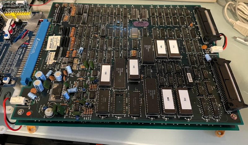
Back to this article, it’s not like arcade operators would put up with one game blasting its din over any other in the building. All those games are equipped with volume controls (lower-left corner of the board in the photo, with a provision for a second if stereo sound were available). At the arcade I worked at throughout most of the 80’s (manager and game tech), I kept the games at a low enough level to have a conversation at the front entrance without having to raise one’s voice. Our attendants had to be in there for hours, after all.