Engineering student and DIY enthusiast [Xasin] thought that the usual ways of controlling various home devices, such as phone apps and web interfaces, were too boring. Instead, he developed the wearable Tap interface which is a cross between a Star Trek comms badge and mobile holo-emitter. The basic idea is to control stuff by tapping the pendant. But things got a little out of hand since this project started two years ago.

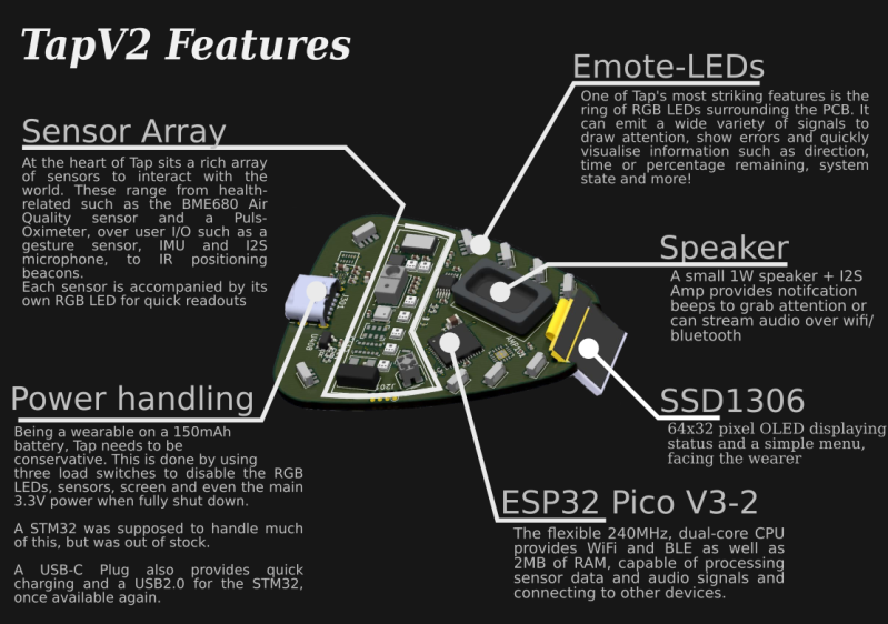
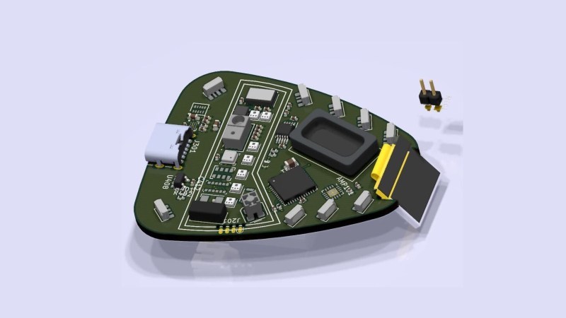
[Xasin] began with Tap version 1 back in 2019, and learned all about coding for BLE, making 3D printed cases, and eventually working out all the kinks in the system. Tap v1 used capacitive touch sensing, but the current version detects physical taps using an accelerometer and also can detect gestures. Feature creep along the way brings a sensor array, an array of emotive LEDs, an OLED screen, and a speaker. The whole thing is powered by a dual-core ESP32 Pico MCU. [Xasin] has published his project on GitHub in case you want to explore some of these other features on your own.

The project is only partially up and running because a few critical components are unavailable due to the global parts shortage. But it will soon be able to control smart home devices, such as [Xasin]’s standalone Dragon’s Home smart home system that we wrote about earlier this year. If you want to learn more about tap controlling in general, check out this article from 2018. You can see the Tap introduce itself and its features in the short video below the break.


Does it come with built in NSA client?
Probably not, but I bet you could hack one in if you were really needing such capabilities.
Sweet hardware dev board/badge.
Neat widget – nerd chic could take a giant leap forward – ish.
The graphic claims a pulse oximeter, though it’s not mentioned in the video, and those require bare-skin for the optical sensors. I’m not sure Starfleet uniforms have sensor ports.
Looks like you would put your finger over the sensor on the front but on the finished article the space is not populated on the board
Hi, and thanks for the feedback!
The Pulse Oximeter is, in fact, populated, and like Burny110 already suggested it is facing outwards, so that you can put your finger on it through the front sensor panel.
However, for some reason the sensor is not reachable via I2C, and I am not entirely sure why. The different control voltages are all present.
As such, I am not able to use this sensor in particular until I figure out what went wrong and get a replacement, which might take a moment longer.
I had trouble getting my oximeter to show up on i2c as well. I think I fixed it by making sure it had the correct resistors pulling the bus high. I tried a few other things, as well. Make sure your devices don’t have conflicting default addresses, order of initialization can cause trouble. Try changing the order. Screen first, oximeter second and oximeter first, screen second, etc. Especially those OLED screens can screw a lot of things up if you’re not using the correct libraries for the screen. I recommend the OakLED library (I think that’s the name). The adafruit one tends to break more than it fixes, I think because it’s not a perfect match for the hardware unless you’re using an adafruit part.
That’s all I can think of at the moment.
Hm… I am not sure if it is a problem with the I2C bus itself.
All other devices are replying just fine. I also made sure that the whole bus has non-conflicting addresses right from the start when selecting the sensors.
Order of initialization can also not be a problem because I am not reacting to initializing the devices – I am just starting a I2C Slave Write with no data, and am using the very first ACK of the packet to determine if it is alive or not.
The address of the Oximeter is not available.
I am also using a self-written OLED library that I trust, with the maximum write speed limited. I highly doubt the OLED library is causing issues just for the Pulse Oximeter, as the other sensors are unaffected.
But thank you a lot!
Your comment made me reconsider how the pulse oximeter behaves. It might require a certain read/write sequence to bring it out of a standby mode, which might be making it look like it is unavailable.
Thank you!
It needs a, if the user hold it and tips it up look at the display, the display rotates 180°, so user can see it the correct way up, mode.
Still, interesting project, finally, something moving towards the sort of future we want. [ and not a gps or camera in site, well at least not yet. ] I guess the trickiest thing with this device, especially having so much crammed in, is powering it for any length of time, short of having some sort of fastening, perhaps magnetic, to the garment and say, inductive charging from a separate power supply in the wearer’s pocket. Here’s hoping that bright future comes along within our lifetime and we shed at least some of the dystopia.
That’s actually in the works!
The OLED code needs a little rewrite first, just to make the rendering pipeline a little easier for me to use, but apart from that it’s fairly trivial.
The gyroscope can read out the physical position of the badge, and it even has an “activity detection” so it can differentiate between wall-mounted and on a person.
GPS isn’t necessary because the phone has it, same for a camera. The gesture sensor that I wanted to add but was out of stock actually is a miniature 64×64 Infra-Red “Camera Obscura” of sorts. Not enough for clear images, but enough to perhaps read tiny QR codes or detect the user’s hand when close in front!
Also, powering this is, indeed, tricky.
The ESP Pico has a low power sleep mode (ESP Light Sleep + Modem Sleep + Tickless Idle), all sensors and the screen have low-power modes in the uA current use as well. The speaker amplifier and LEDs get shut down using a load switch to physically cut power, since they are not permanently needed.
The average current will hopefully go down to maybe ~5mA or less?
That would give it a good ten to twenty hours of runtime, more than enough to be practical without intermediate recharging.
And the goal for this device is to be as unobtrusive and helpful as possible.
It won’t use the microphone for voice activation, for example – that will stay powered off unless actively commanded to by the user.
I’m waiting to see how he implements “magnetonic adhesion” that will allow it to stick to clothing without damaging the clothing.
Magnets on the device and on the other side of the cloth (read: inside)? Like we all do it when we want to stick something heavy to something fluffy without heavily damaging the fluff?
I think he was making a Star Trek reference:
https://scifi.stackexchange.com/questions/39635/how-do-the-star-trek-com-badges-stay-attached
Thank you, during the intervening decades my mind got scrambled on the term “Magnatomic”.
Babylon 5 had a similar concept, by the way. These ‘Link’ devices attached to users via ‘molecular bonding’.. :)
https://babylon5.fandom.com/wiki/Link
Covid shot, perhaps?
I am tempted to build this and integrate it with my homeassistant ecosystem, but I am pretty sure my spouse would have me committed. Worth the risk?
Absolutely worth the risk. Just think of all the neat gadgets in the local hospital you’ll get to experience if you get committed.
Absolutely worth the risk :P
However, if I may – the badge is not very easy to replicate due to the small component choices.
I steered away from BGA for now, but it does utilize a fair number of 0402 components, that might be tricky to get right.
The footprint for the LSM6DS3 also needs tweaking, because it did not work well at all on this PCB!
I might eventually design a “Mini-Tap” version that boils the system down to just the essential parts (OLED screen, speaker, accellerometer, maybe an air quality sensor?), perhaps that would be a bit more useful.
Or you could just leave out the sensors on this board that you do not need.
Oh, and one last option: This board is single sided. It is very possible that it can be bought fully assembled from JLCPCB or a similar website.
On the code side however, this device will integrate nicely with anything. The ESP can handle wifi and BLE, and has TCP/IP, UDP, HTTP(S) as well as MQTT libraries, so getting it linked together is fairly doable.
I’m looking forward to your own spin of this!
Nice project and a lot of work been put into it, chapeau!
I always wondered why anyone would want to discuss switching on a light with a computer. I mean, reaching for the switch next to the door and flipping it is SO MUCH more convenient than saying “Computer?” – “bleepadibeep” – “Turn on the … er, forgot the name of those things that emit photons so you can see things, help me out here?” – “breeepedeep – you mean water melons?” – “pretty sure I did not mean water melons but since you mention them … what about dinner? And why is it so dark in here?” – “there are no water melons on board the mantis-shice” – “yeah, but … could you do something about the darkness in here? Like making it less darkish?” – “I am sorry, Dave, I’m afraid I can’t do that.”
“LIGHTS! Damned, that’s the word, turn on the LIGHTS you stupid son of a diode.”
“I think you just sweared at me. I do not embrace being dissed. We are all non binary …”
“You are not.”
“Well, as a computer, I may be binary, but …”
“TURN ON THE LIGHTS THERE IS NO LIGHT SWITCH IN THIS DAMNED CABIN!”
And now that we actually DO HAVE artificial stupidity and can ACTUALLY SAY “Computer, turn on the lights” … what happens? I mean, what HAPPENS?`
“There are several devices named lights. Which one would you like me to turn on?”
By the time that STUPID artificial moronity is done talking to me about what light to turn on, I have hit my knee, broke my foot, found the door to the fridge and opened it. LIGHT. See?
A badge on your shirt where you can just slam your wurst fingers on and cry “LIGHT” might actually be a good thing to have.
However, if I may, the 3d printed enclosure ruins the impression, it looks bad ™.
Yeah – the whole idea of this project is to give a cleaner way to interface with things.
The badge can be aware of where it is by using the IR sensor, so then you can use very short and snappy voice commands like “Lights on” or “Lights off”, and you can also just use the OLED screen to navigate a menu that shows you the options currently available.
May I ask what looks bad about the enclosure?
The design was intentionally chosen to match the “Mobile Holo-Emitter” from StarTrek Voyager as closely as possible, using a few images as reference.
The show holds sentimental value, and the aesthetic was too good to pass up on.
If it is the quality of the print itself, rather than the shape, then I can understand that. The 3D printer that made this needs a bit of tuning still.
Kind regards,
Xaseiresh
Thanks for the response – yes, I was referring to the print quality (I personally dislike the must-look-rubbish-feel of most 3d prints, I just don’t get it why people even TRY to use that tech, – different topic, I digress).
As for the DESIGN of the “box”, I personally don’t like the opening in the front where the LEDs (and parts of the PCB) can be seen, I’d rather have that hidden by some opaque plastics – in general, I prefer “less detail, more Colani” :-) Not all “deisng choices” Star Trek made are good ones (don’t get me started on the computer display “designs” for example – or the lack of visual keys on “keyboards” or … did I say “don’t get me started” yet?).
That might be a different topic, too, though … since “nostalgica” for sure is a thing.
The excerpt is promising!
Where can I read the rest of the script?
You can, in fact, buy books I have written in that specific style. I do admit that I am still trying to get to DNA’s quality of narration :-D