I have a confession to make. I write about a lot of projects for Hackaday, but there are very few I read about and then go actually build a copy of it. I don’t have a lot of time and I’m usually too busy building my own stuff. But once in a while, something strikes my fancy and I’ll either raid the junk box or buy the kit. The most recent case of that was the PX-41C, a replica of the classic HP-41C.
The HP-41C is a somewhat legendary reverse-polish notation calculator. I still have my original HP-41C from 1979 (a very low serial number). It is still a workhorse but at 43 years old or so, I don’t like to leave it hanging around or near anything that might damage it. It has enough wear from the daily use it received 40 years ago. Sure, I have great emulation on my phone and I use that too, but the PX-41C kit looked fun, and with all through-hole parts it would be a quick build. The black Friday sale on Tindie sealed the deal for me.
Start-Up
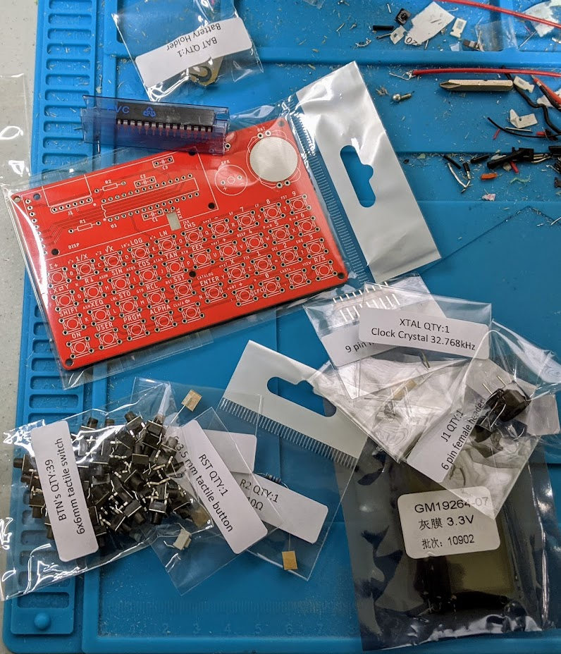
The kit arrived on the Saturday after Thanksgiving, I decided to tackle it while waiting for some 3D prints. The components were all nicely bagged and marked. Tearing into the bags was a bit frustrating, but not hard and it did keep everything separate. There was a bill of materials, but — I thought — no instructions. Turns out the last part of the bill of materials is a link to some instructions. They aren’t much and I didn’t realize they were until after completing the board, but it isn’t hard to figure out. All the parts are marked on the silkscreen and you can probably figure it out — with a few caveats.
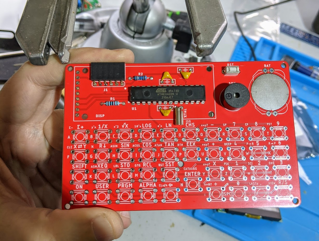
Several components go under the LCD display and that is soldered in, so you need to put them in first. I wondered if you should install them on the back of the board, but the pictures showed them front-mounted and you realize pretty quickly you have to bend them down to let the LCD sit flat. The instructions, if you read them, do mention this.
Once I had everything but the switches done, I powered up to make sure it all worked. It did — or, at least — it powered up and said MEMORY LOST.
Switches
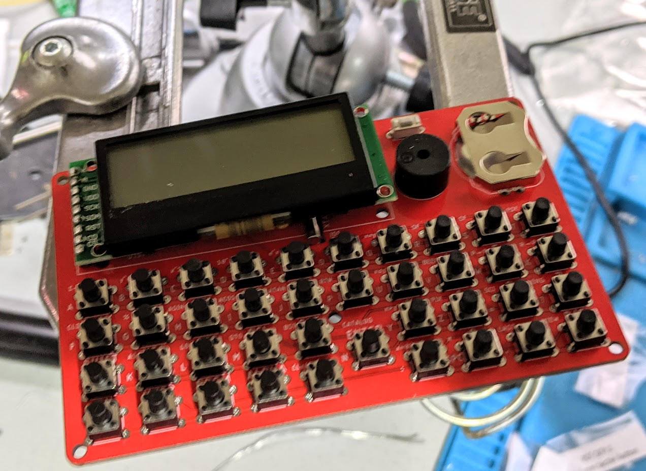
There are 39 little tact switches to install. Luckily, they have little legs that spring into the holes, so it isn’t very hard. However, they can pop out, so I suggest doing a column or two at a time. One switch was a little bent out of shape but there was an extra, so I didn’t bother trying to unbend it.
With a few keys in the bottom right corner, I could power on and do a few quick calculations with no problem. The board takes a CR2025 and I only had a thinner battery. A dime made a good spacer and let me fit the thin battery and get the thing working.
Configuration
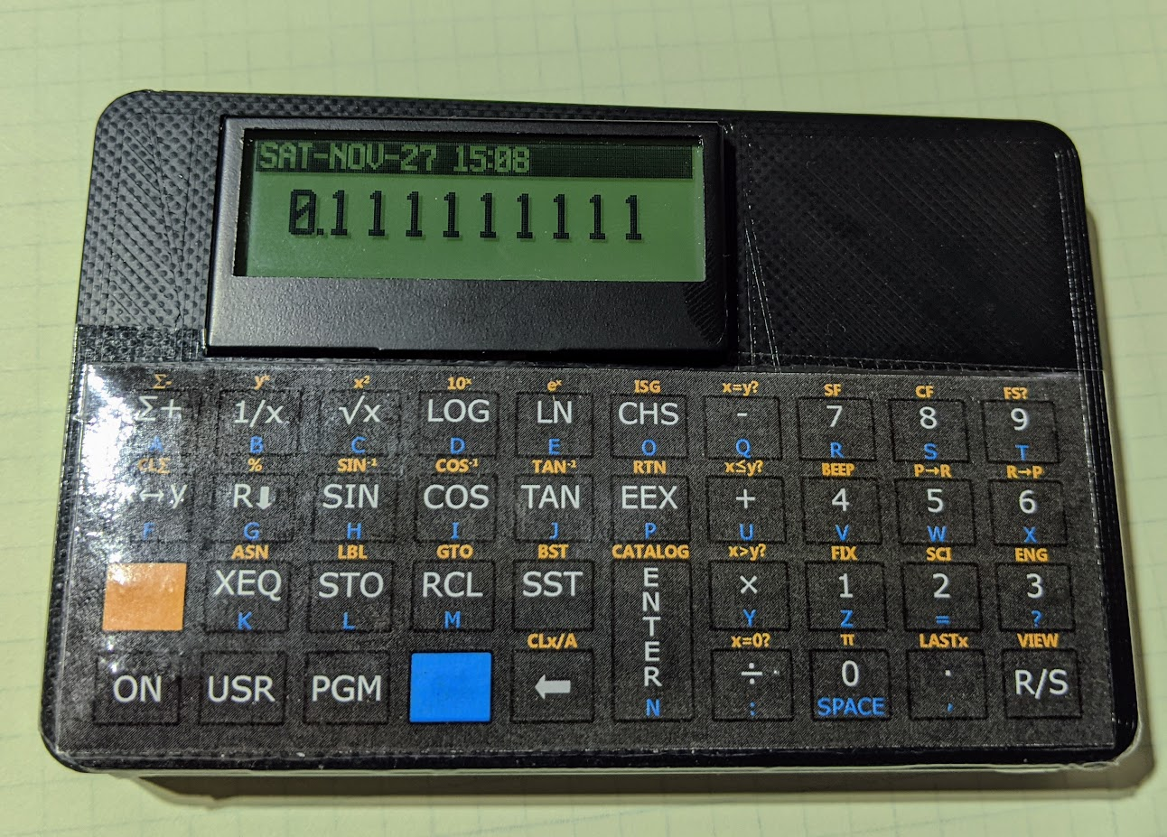
The board has a backlit LCD and a clock — features a regular HP41C didn’t have. However, I didn’t see an obvious way to set them. I had found the documentation by then and it said to hold the 0 key while powering on to get into the configuration menu. Turns out, it is the divide key, which took a minute to figure out. In addition, the keys to operate the menu system are a little wonky (but, in all fairness, the firmware put a help message on the screen until you release the divide key).
Just in Case
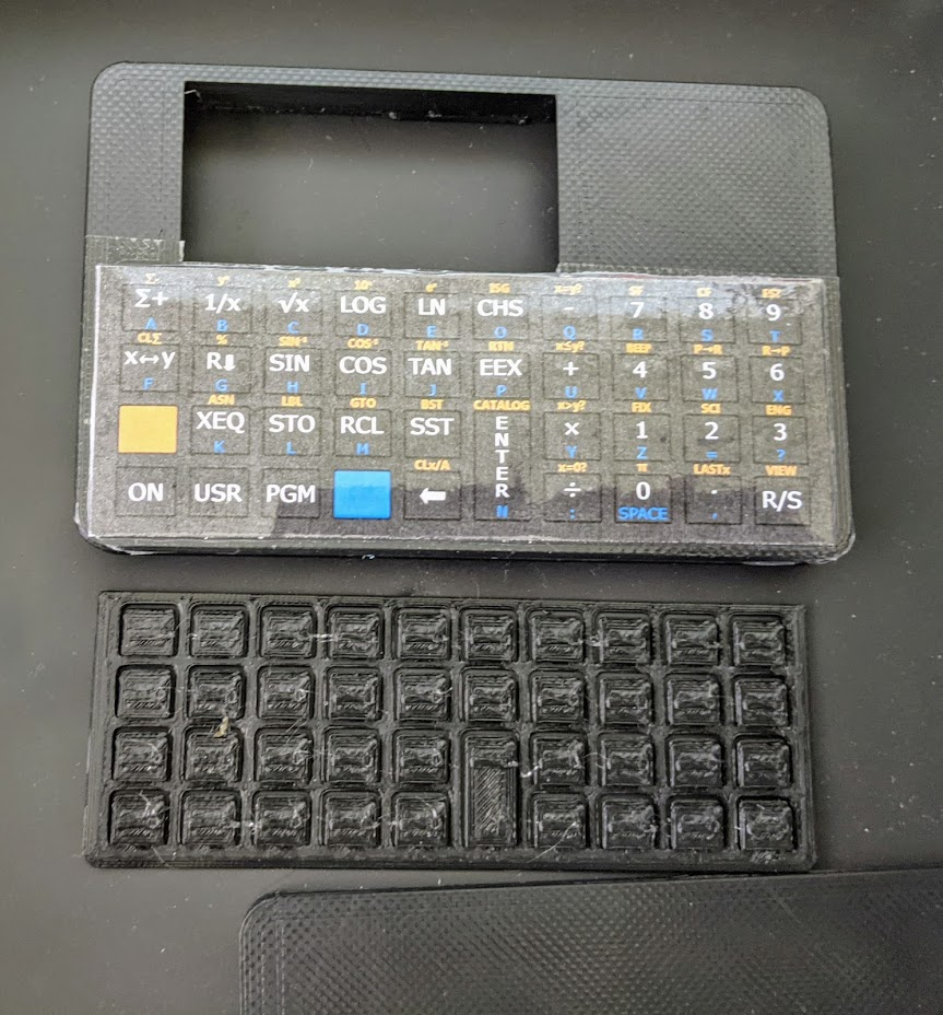
There is a 3D printed case and a way to print an overlay for the keys along with a springy key matrix. They were nice enough to send me these already made up, although I’m not sure that’s always included. The overlay looks great at first, but if you look closely, it is taped down and that detracts a little from it. Don’t lift up the tape! It will ruin the overlay.
The case looked good, and it is fairly simple. There were a few problems, though. First, the LCD was poking up at an angle. The instructions tell you to tape it down to the CPU, but that didn’t really help. After taking these pictures, I pulled the LCD off and reinstalled it carefully with new headers and had it come out nice and flush.
The other problem was that the R/S key in the bottom right corner didn’t want to work with the case in place. Sometimes it was inoperative. Sometimes it would work but didn’t click like the rest of the keys and was more like a touch panel. Sometimes it was stuck pressed down.
I tried filing the case a little but that didn’t seem to help. There are some nubs that keep the board from coming down too low on the key springs. It looks like the case was warped enough to have that corner a bit lower than the rest. If you left the back off and pushed on that corner, it would reproduce the problem, but the other corners were fine.
I thought about reprinting the case myself — I have enough 3D printers, after all. But I finally made a little paper shim to make the stop in that corner a little thicker. I just took a small strip of paper and folded it many times until it was about the same size as the stop and inserted the stop into the paper making a sandwich where the paper was the bread and the stop was the meat. This seems to have cleared up the keyboard issue. It doesn’t look like the problem was related to the key installation, but anything is possible. I’m pretty sure it was just a subtle warping in the case.
Last Impressions
For the price (about $40) this is a fun kit and is actually useful. It would be nice if the LCD had a socket. It would also be nice if the overlay install looked cleaner, but for a casual glance, it is fine and it still looks better than just a bare PCB with keys — unless you like that sort of thing.
I haven’t tried to see if the emulator will do synthetic programming yet, but it is on my to do list. Otherwise, I now can use my HP41C with no phone and without risking my real one. After forty-some-odd years, it can use the rest.
For some reason, the projects I tend to build after writing (or reading) about them are mostly for retrocomputing. I built the KIM UNO (and repurposed it for the 1802). I built a PiDP-8 (and need to find time for the PDP-11 version). Possibly my favorite was the $4 Z80 which I actually added a bit to, software-wise.


but without the HP style buttons?
Getting a retro unit with buttons that meet the “feel” and reliability of the original HP buttons is difficult.
SwissMicros does a good job of it. I’ve also seen a few 3d-print (SLA) over PCB tactile switch setups that match the old HP ones pretty well.
So, even though it has a Real Time Clock, it doesn’t have the clock functions of the HP-41CX?
i need fuzix
My first “real” calculator was an HP 11C. I immediately fell in love with RPN; it was a natural to the way I think. Further, it was my first introduction to progamming. I used the HB Basic to run engineering beam bending calcs for concrete form work. This looks to be an intriguing project.
I’d buy one of these in an instant if it was in a true HP41C vertical orientation.
I never liked the horizontal orientation of the HP-15C.
Exactly the opposite in that I like the horizontal orientation. My first HP ws the 11C, then when I got the 15C and 16C my sister took the 11C. As said above, RPN is ‘natural’ to the way I think too.
I might have to to check this kit out. Thanks for the article. I enjoyed the PDP 11 build (was actually working with it last night for a bit). I sent a message a couple months ago to see about getting a PDP 8 but never received a response on that request. Oh, well.
The display on the kit is so much better than the ortiginal! I may have to buy one of these.
I still own and use my 41C which my dad bought me in 1981. Always get a kick knowing that it was carried on early space shuttle missions!
I so WISH they would have added a physical on/off slide switch right next to the reset button. That ATmega 328 sips power when sleeping, but it WILL drain that coin cell eventually. Adding the slide on/off switch would have solved that problem. Even if you argue the deep sleep draws “negligible” power next to the shelf life of the battery, I still do not buy it. The shelf life of coin cells in my experience is far longer than manufacturer published, plus they’re over-priced, and (most important) it just BOTHERS me when a battery operated device like a calculator cannot be easily and fully turned off!
The ubiquitous “transistor tester” has a nice power-off circuit.
It’s made of a few BJT’s (which generally have lower leakage the MOSfets) and the “off” current (from a 9V battery) did not register on my DMM (100nA resolution).
I’m a big fan of hard power switches too.
That well-known BJT trick is excellent, but really useful only when you have a bit of voltage headroom to spare, and don’t have a lot of dynamic range in your power requirements. The transistor tester’s load and its 9V battery is ideal.
The 3V from a coin cell won’t work so well, especially with a widely varying load.
A physical on/off switch would power down the ATMEGA328 and you would lose all Memory. All storage/programs would be lost.
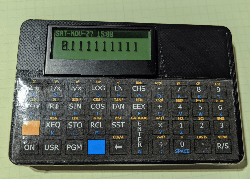
is possible add more numbers on screen? i need 20 numbers on screen
0.1111111111111111111
20 digits exceeds the numeric precision of even double-precision floating point by several orders of magnitude.
The real 41C has only 13 significant digits.
I don’t know what library this FauxHP uses, but Arduino floating point on that processor has only 6-7 digits of precision.
gmp
etc
I is an emulator. So it runs the same firmware as the original.
Or you can buy from ebay a new HP20b or HP30b calculator much cheaper than the above tindie project and then flash it
with the WP 34S firmware to transform it in a scientific RPN calculator. You will get a 32bit AT91SAM7 processor instead of
the 8bit ATMega328, a proper case and the classic HP buttons. Decals for the WP34 are also readily available.
Loved my 25 and 41C, but now I have an emulator (V41 on the computer, i41C on my iPhone) and it’s just fine. I get my RPN fix virtually, though I do miss that lovely HP button feel.