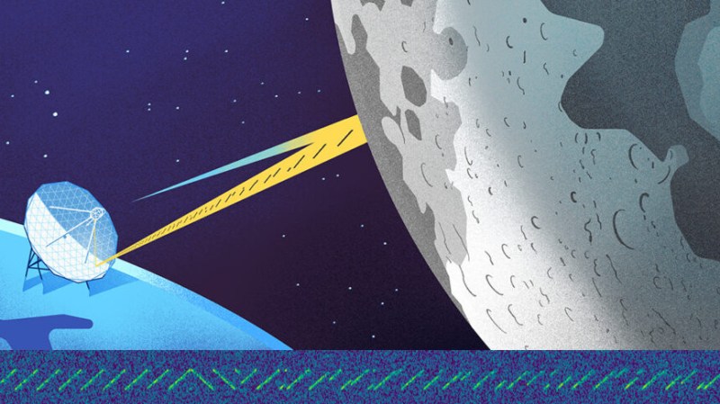
The LoRa radio protocol is well known to hardware hackers because of its Long Range (hence the name) but also its extremely low power use, making it a go-to for battery powered devices with tiny antennae. But what if the power wasn’t low, and the antenna not tiny? You might just bounce a LoRa message off the moon. But that’s not all.
The team that pulled off the LoRa Moonbounce consisted of folks from the European Space Agency, Lacuna Space, and the CA Muller Radio Astronomy Station Foundation which operates the Dwingeloo Radio Telescope. The Dwingeloo Radio Telescope is no stranger to Amateur Radio experiments, but this one was unique.
Operating in the 70 cm Amateur Radio band (430 MHz) meant that the LoRa signal was not limited to the low power signals allowed in the ISM bands. The team amplified the signal to 350 Watts, and then used the radio telescope’s 25 Meter dish to direct the transmission toward the moon.
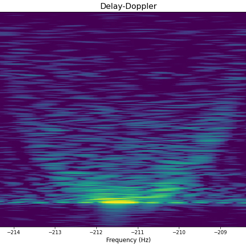
The result? Not only were they able to receive the reflected transmission using the same transceiver they modulated it with — an off the shelf IOT LoRa radio — but they also recorded the transmission with an SDR. By plotting frequency and doppler delay, the LoRa transmission was able to be used to get a radar image of the moon- a great dual purpose use that is noteworthy in and of itself.
LoRa is a versatile technology, and can even be used for tracking your High Altitude Balloon that’s returned to Terra Firma.


Interesting, have been watching Lora for awhile. I wonder what it would take for an back yard experimenter to do this without having to use a 25 meter dish.
Alot hobbyists use smaller set ups to moonbounce ft8(instead of lora) at 1296mhz. I would like to see this done closer to 6ghz so you could use a much smaller dish maybe an old direct TV dish or something, idk
1296millihertz dish must be enormous.
Well millihertz would be mHz so you are splitting hairs there.
Unfortunately, the 23cm band is defacto dead.
In Europe or Germany, at least.
For some reason, ham gear manufacturers did stop to provide 23cm capable radios roughly two devades ago.
No idea why. Maybe because it was too difficult/costly to implement, not sure.
Maybe, because 23cm wasn’t covered by the CEPT licenses also (in Germany, Class 3 originally covered 2m/70cm only;
later on, Class E also included some HF bands and recently, a few more bands above 30MHz).
https://en.wikipedia.org/wiki/23-centimeter_band
That being said, I remember my father used to do moon bounce on two meters using two 18 elements antennas (long yagis)..
When I first saw this I thought “I wonder is it an ad” for the Semtech LR1110 chip with a built in passive WiFi MAC address scanner and GNSS scanner and a LoRa transceiver. So I checked the datasheet and the first version of this chip 1.0 was 2020-02 so it is probably not an ad.
But if it was I called it! – https://hackaday.com/2020/03/21/high-power-lora-and-tropospheric-reflection-experiments/#comment-6230266
How is lora 430 MHz?
The chip used can tune LoRa to any frequency between 150MHz and 960MHz to support worldwide frequency allocations. The PLL frequency is set using SPI register 0x020B (A SetRfFrequency command which passes a 4 byte frequency parameter in Hz)
Oh. I didn’t know that, either. So does that mean it can’t be operated in the classic two meter band (144 to 146Mhz / to 148MHz) without using a converter ?
My answer would be maybe/probably, since to meet specification it much be able to tune down to 150 MHz and since it is a 4 byte frequency in Hertz I do not see why 0x08 0xB3 0xC8 0x80 (146,000,000Hz) would not be a valid input value, but there might be an analogue band pass filter, but even it would probably have a 3dB roll off at a guess so maybe/probably it might work ? Buy one try operating it outside of its tested frequency range specification and maybe it might work ?
Look at the RTL-SDR it’s tuner chip (R820T2) is officially specified to work correctly from 42 to 1002 MHz but most SDR hardware that use that chip can tune from 24MHz up to 1700MHz or one of the tuner chips used in the HackRF (RFFC5071) which has an official frequency range from 30MHz to 6000MHz has been used with an additional tuner to go from from DC to 7250 MHz.
I think 0x57 or 0xZZ and such are for the C pre-prossor and are not base 16 numbers. If you are not writing code there isn’t anything wrong with just writing them out and say 08B3C880 hex, or 08B3 C880 or anything human. Anyone used to hardware will break it into bytes or words mentally and can probably picture the bit patterns without thinking (as well as the ASCII).
I see, makes sense to me. Thanks a lot for your explanation! 🙂👍
Nice. I’ve wondered what it would take to image in real time through atmospheric obstacles such as clouds and fog, and contaminants like smoke, that don’t have the limitations of thermal imaging or image intensifiers. I expect smokes to be more difficult than H2O based photon scatterers. Perhaps radio is the way to go?
Imagine having a HUD in your car that shows you the path ahead, allowing you to confidently drive through thick fog banks, sand storms or wildfires, using radio imaging technology.
EME Info: 432 and Above EME Newsletters by K2UYH et al.
EME JT65B-C is working with 50W , single Yagi 2m/70cm,
but the partner station is big (antennas-power),
JT65A 50 MHz, Q65 mode 23cm — 3cm
And, some microwave (Dubus) EME contest CW/SSB modes only
nothing any digital modes …..
I am an an amateur radio operator and have been experimenting with LORA for a couple of years. I have established a link between out local mountain top repeater and my home about 15 miles away. I am the tech guy and a retired electrical engineer ( nonRF). I have tried 430 MHz and 915 MHz and both have worked fine at 100 mW. I have been puzzled as to how to ID when operating it 430. We have a coordinated data link to use but the ID perplexes me. I am also a bit confused as to the bandwidth limitations of UHF. Any thoughts?
Bob K3DBD
Has anyone achieved a moon bounce from their garden using Lora 433 MHz or 915 MHz ?.
I know this is an old but may I ask how to “convert” the above radar image to more eye friendly /