Over the years we’ve seen a number of hackers generate VGA with 74xx logic chips, but they’ve generally not been the most practical of builds. Often put together as part of a competition or purely for the challenge, these circuits are usually implemented in a mass of jumper wires and often take up multiple breadboards. Not exactly something you can toss in a drawer when you’re done with it.
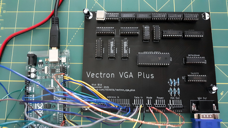
But the Vectron VGA Plus, created by prolific hacker [Nick Bild], manages to improve on things considerably. Designed specifically to be smaller and simpler than its predecessors, the custom PCB contains far fewer chips than we’re used to seeing for this kind of thing. At the same time it provides a handy header row along the bottom that allows the user to connect whatever they’re working on, from microcontrollers to retro computers.
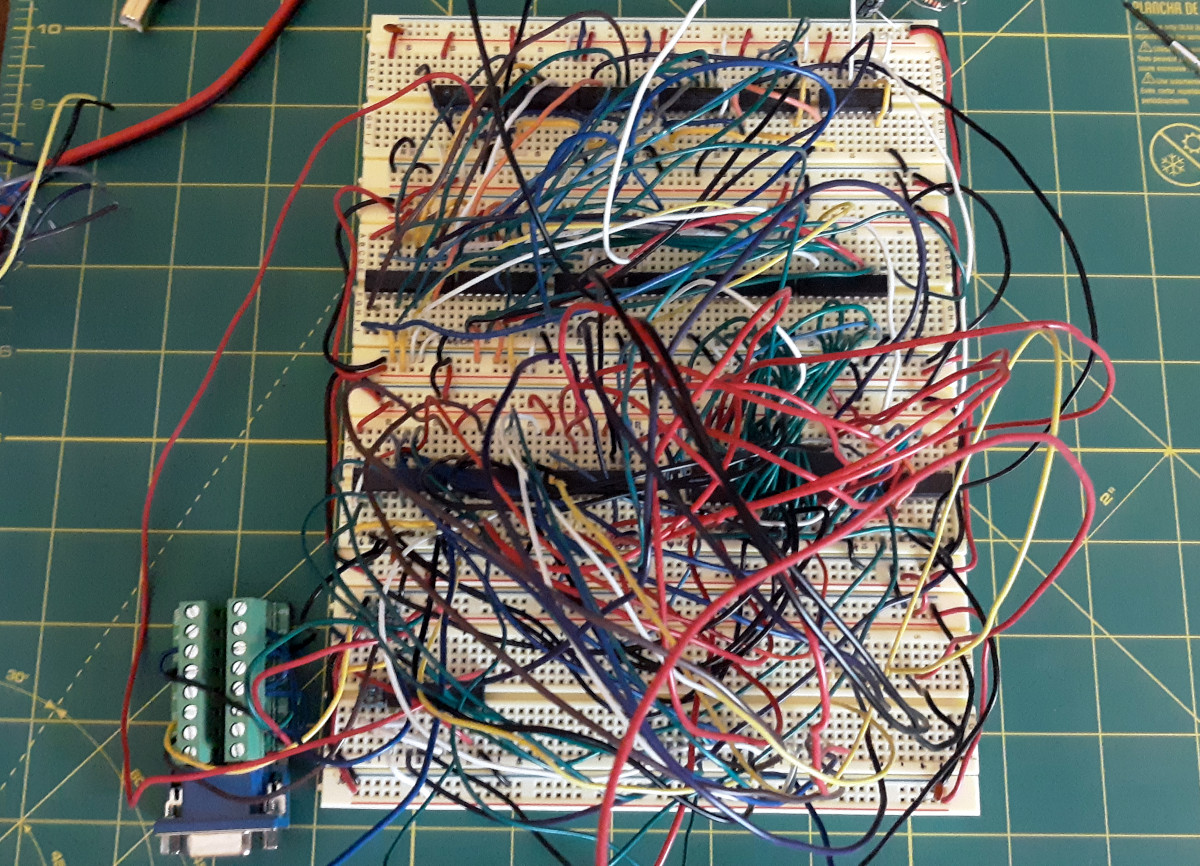
It looks like the PCB could still be shrunk down considerably if you’re really looking to maximize desk space, but we imagine for his purposes, [Nick] felt this was more than compact enough. Especially when you look at what the same circuit looked like during the breadboard phase. Yikes.
So, what did it take to simplify this 640 x 480 VGA interface? The short answer is adding more RAM. Wherever possible, dedicated hardware was replaced with software operations that could be performed by the externally connected device. [Nick] has provided some sample code for the Arduino that lets the microcontroller push data into the board’s memory and take control.
We can trace the origins of this project back a few years, to when [Nick] was working on adding an LCD to his homebrew 6502 computer. A few months later he put together the earlier version of this board, the Vectron VGA, before switching gears and handing VGA generation duty over to a FPGA. We’re excited to see the next evolution of this project, and given the track record of this particular hacker, we shouldn’t have to wait long before it hits our inbox.


I have the same dejavu feeling.
No, a different project based on 7400 series logic was featured a few days ago.
The fact that there’s only two bypass capacitors for the whole board and it still works is impressive.
Might be those IC sockets that have a built-in decoupling cap under the seated chip.
Or SMT’s on the bottom. That as well as 10k pull-up resistors were our very first SMT application in the early 90’s.
Given that there are 3 ‘spare’ bits on the ram, why isn’t there 6bpp (or 2bpc) colour?
“………this 640 x 480 VGA interface?”
Actually, it’s a 320 x 480 interface that complies with 640×480 VGA standard timing. As described, the pixel clock is derived from the standard 25.175 MHz master by dividing by 2. Unless you resort to more complex circuitry with interleaved address counters and RAM, you won’t reliably get 640 horizontal pixels with plain old 74HC/74LS logic. That requires a pixel out every 39.7nS and the “typical”, let alone the worst case, specified propagation delays of the cascaded logic add up to about that if not a little more.
It doesn’t really take that much extra logic to fully decode both the sync timing and the blanking intervals in hardware and that does come with the convenience that you’ll never have to bother programming the RAM for timing.
It doesn’t look like the blanking intervals are decoded at all in this design, so there are areas of memory corresponding to these intervals that will need to be zeroed upon initialization and then avoided thereafter.
I guess deriving the sync signals from RAM is neat if the goal is minimal hardware, but a skim of the schematic doesn’t reveal anything obviously specific to prevent the design from putting out un-blanked video and random data streams on the sync lines after it is initially powered up, before you’ve had a chance to program it. Some of my old and dumb (analogue) CRT (S)VGA monitors would throw a tantrum if fed such a signal.
Hmm, skimming the schematic a little more I notice that the data port is unidirectional – that is data can only be written to video RAM and not read.
I get that a goal here has been minimal hardware, but that’s a simplification that might go a little too far when you realise the capabilities lost by not being able to read the video RAM – block copying part of the display to another other part, saving generated video display data and collision detection, for example.
Screen painting routines similar to MS Paint’s bucket fill require the last one. I wrote a primitive version of such a routine to demonstrate the capabilities of my own 74-logic VGA video card design. It was used extensively in this demo (to fill the body of the vehicle being drawn):
https://www.youtube.com/watch?v=hkUVOHU8gik
All Hail Vectron!
https://www.youtube.com/watch?v=icTrzUuWlHI
In other more relevant replies. I had an industrial machine delievered a few months ago and it only had VGA. I was aghast. Turns out a lot industrial machines use VGA even now so replacements tend to need it. This could prove really useful for those trying to retrofit old CNC’s and the like.
Not that it may help you, but I find that most flat screens in 2nd hand stores are VGA, and for under $25.