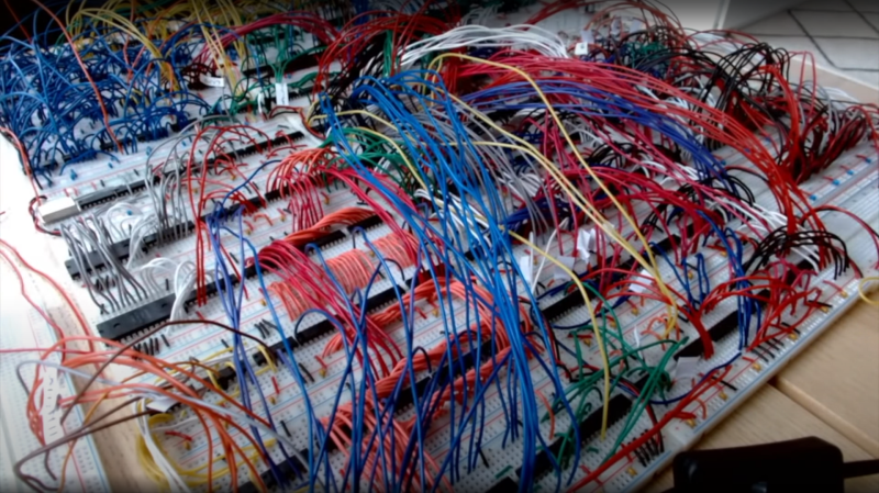
These pages have not been exactly devoid of home-built computers, with those constructed on solderless breadboard less frequent, but still not rarities. But what is more of a rarity is this ground-up 8-bit 74xx logic-based computer (video, embedded below) with full source, an emulator, assembler and test suite. [JDH] spent a solid couple of weeks working late into the night to build this, and the results show for themselves.
The new JDH-8 is now a figment of reality.
The architecture is a traditional 8-bit load/store microcoded processor with the microcode stored in easily programmable AT28C64 EEPROMs for ease of tweaking. The address bus is 16-bits, which is quite ample for this, and puts it in line with (admittedly more sophisticated) 8-bit micros of old such as the 6502. There is also a hardware stack, and a discrete-logic ALU as well! Finally, since that wasn’t enough work already, he added in his own discrete logic video controller.
There are sixteen instructions covering memory access, ALU operations and I/O operations. One of the great things about this project is that [JDH] readily admits the mistakes made along the way, and how the architecture didn’t need to be this complex. One example is that hardware stack wasn’t really necessary as it could just have been implemented in software. Also, due to the implementation, memory accesses were so fast compared with the achievable cycle time, that there really was no point to using load/store architecture at all! Still, [JDH] had fun building and programming it!
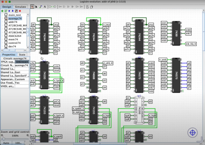
It was interesting to see the use of LogiSim-Evolution to debug first a high level model of the architecture and then the translation into TTL chips. This scribe wasn’t aware of that tool (the shame!) but is going to try this out real soon.
All code for the software side of things can be found on the project GitHub. Perhaps the hardware design will appear there as well, be at the time of writing we couldn’t seem to find it.
Can’t get enough breadboard computers? (We can’t) check this out from last year. Stuck for a suitable enclosure for your latest bread breadboard computer? How about a bread bin.
Thanks [BrightBlueJim] for sending this in!


Hat’s off to this young man for his engineering curiosity and determination!!
Is “dedication” another word for insanity perhaps?
Just kidding! Great work!
Without DMA and at least 256 differential line-drivers, a computer is just a toy.
Ooh, That logic simulator looks nice! And it’s missing from Hackaday’s roundup earlier this year!
Logisim Evolution
https://github.com/logisim-evolution/logisim-evolution
Great work !. I just tried the logisim evolution model and some TTL chips, that do not come standard either in 3.5.0 or 3.7.2, are missing: 74151, 573, 279 and so on. Which library did you use that contained these chips ? (I use the jar version of logisim). Thanks !
I remember him saying in one of the videos, that while he includes the logisim files he used for simulation, these are mainly for study, as they depend on models he had to make himself for some of these chips. I think he also said that at some point he may be able to release these models. Or maybe he said something like “never in a million years”. I forget sometimes.
Got a link? I did look and didn’t find it.
I think it’s both fascinating and encouraging that people still care for the foundations of electronics and keep basic knowledge alive in our collective memory.
As long as such knowledge keeps being preserved and shared, future technology can be understood and fixed/altered/..
Thus, people like this are my heros.😎👍
This guy definitely has debugging and troubleshooting skills. :)
I thought his use of a different set of chip models for use in laying out the circuit on solderless breadboards was interesting. Where you and I might use something like KiCad, that has a schematic editor and a completely separate PCB editor, and each component has both logic symbols and package drawings, he just used the same editor but with different component libraries for first the gate symbol schematics, then the package physical layout. It’s kind of what happens when someone whose specialty is in one discipline (software in this case) crosses the border into another discipline (computer hardware design), where he isn’t aware of the standard tools and ends up building his own. And in this case, he wasn’t interested at this point in laying out PCBs anyway, so the only available tool I can think of for doing what he did – translating from schematic to breadboards – is Fritzing. Which to my mind means that developing his own solution probably was superior anyway.
Did a project like this as a freshman at Cal Poly Pomona in 1985. Ours was on a breadboard with wire wrap. Eeprom, ALU and 74LS logic programmed from a spdt push button with BCD display. Project was called Student Project In Digital Design. StuPIDD Professor was a family friend who has since passed, Dan Nesin. One of his prior students was the lead developer of the Apple Lisa, the precursor to the Mac.