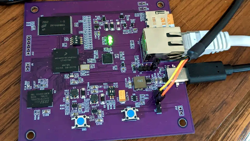
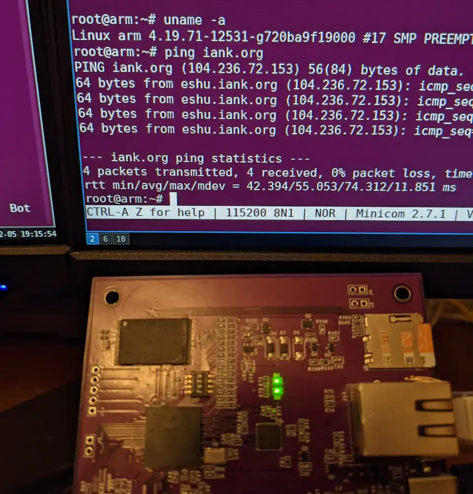
It’s truly incredible what the hobbyist is now capable of. While it would have seemed all but impossible a few years ago, we’re happy to report that yet another dedicated hardware hacker has managed to spin up their own custom Linux single-board computer. Creator [Ian Kilgore] tells us the only goal when developing CATFOOD (yes, that’s the name) was to gain confidence with at-home board production, so it looks like a success to us.
 To those who’ve been keeping an eye on this sort of thing, it will probably come as no surprise to hear [Ian] was inspired by the work of [Jay Carlson], who arguably kicked off this whole trend when he put together a bevy of homebrew Linux boards in an effort to compare different System-in-Package ICs. His incredibly detailed write-up of the experience and lessons learned along the way has emboldened other brave souls to take up the challenge.
The USB-C powered board uses an ARM i.MX 6ULL processor and features DDR3, NAND flash, and an Ethernet interface. That last one was the biggest deviation from the reference design, which meant it took a little fiddling to get right. For anyone playing along at home, [Ian] collected up the lessons learned while developing CATFOOD, bringing the whole learning experience full circle.
If you’re interested in more homebrew Linux SBCs, we’d highly recommend reading up on the WiFiWart developed by [Walker]. Over the course of about six months, we got to watch the open hardware board go from concept to a diminutive first prototype.


Power over Ethernet is common now with homes having switches for video cameras and wifi AP.
POE indeed is handy.. But, do not overlook the stupidity of the “Low Bid” contractor.
One customer asked me to repair his local network, and after a quick look around, I found Ethernet cables stretched along a storage area, and product pallets squashing the cable.
The seemed to place the voltage where it was not needed. I replaced some cable, and jiggered the network design a bit, and collected my pay.
A worker bee decided he knew a better way and un-jiggered the cables.
Who knew that some of the computers didn’t like voltage on their network cables.
So I (They) ended up with a printer, a VOIP phone system and assorted computers belly up.
Ah, the good old days.
There are several PoE methods—the old ones hardwired power onto unused pairs, but the new ones negotiate the power and therefore aren’t dangerous to devices that don’t expect it.
Some switches have PoE built in, and you can just use it as a switch which will provide power, only to devices that use/ask for it.
Anything that supports gigabit is going to feed each leg of the DC supply as a bias on a pair. The isolation transformer’s primaries have a center tap for injecting or recovering the bias. Providing the lost isolation for the supplied or received power is the main reason why active .af PoE switches and devices are so expensive.
There’s a negotiation phase when you plug in the cable, so devices that don’t expect the power should just see regular Ethernet.
The ingenuity of smart people never fails to amaze me. Well done.
But the ingenuity of stupid people continues to amaze design engineers!
B^)
(That was not intended to be a personal attack, so don’t read it that way)
Yes and as maintenance staff you get to see the mistakes of the engineers.
Is the design by any chance made open source and documented somewhere? I wish there was a step-by-step guide to making such boards or at least a fully documented sample project.
The wifi wall-wart project linked in the article links off to its github. The also-linked Jay Carlson article goes over a ton of design considerations, though it doesn’t seem to link off to a repo. Really, after reading up on these three projects, I don’t see why anyone who’s built a few PCBs wouldn’t be able to replicate the effort with a fair chance of success.
If you need help getting going on making PCBs in general, I find KiCad to be a great tool. Working up to an STM32 (or similar) 4-layer board with good design practices should prep you nicely for this, especially if you find an excuse to practice incorporating BGA components, such as a power regulator or some other such IC. DigiKey has a great series on getting started with KiCad, and Phil’s Lab has a bunch of great videos on PCB design best practices (Rick Hartley’s talk on proper grounding is also a must-watch/listen) that will have you designing solid boards with some time and effort.
Thanks for the tips! I somehow overlooked the repo link in the wall-wart article.
I am at the level where I t̶h̶i̶n̶k̶ ̶I̶ can quite comfortably lay out basic microcontroller boards with AVRs, ulitising some basic peripherals (driving motors, CAN communiation, I2C/SPI sensors etc.), and I indeed use KiCad for all those projects, long live the open source!
Linux capable boards just get me extra excited because I heard so much about the awe and mystique of laying out DDR traces and other issues tied to the MMU-endowed chips that it sounds to me like a completely new magic underworld of electronic dark arts, known only to the few elders that became one with the Horowitz AoE. BGA packages and 2+ layer boards seem to be an additional huge challenge. Nonetheless I hope one day I’ll also get to the level of this articles protagonist.
Thank you again for the reply and have a nice day!
There is a huge knowledge gap between your **slow** microcontroller stuff and what you’ll need for DDR traces – namely Signal Integrity.
>few elders that became one with the Horowitz AoE
AoE was a book I used for non-EE majors back in school and won’t get you there. You would want something more like “High-Speed Digital Design – A Handbook of Black Magic” (I used at work) at the bare minimum.
You also want to read up any app. notes by memory chip vendors (e.g. Micron), embedded processors (especially the one you’ll be using) that deals with DDR. Read up as many materials from **primary** source as you can and to put in real work.
I am genuinely stunned about the fact that the title “High-Speed Digital Design – A Handbook of Black Magic” is in fact real. DDR seems to really be the dark art.
How much more does the topic involve in comparison to learing to lay out a microcontroller design? I always thought It was only about the trace distance matching with those wiggly snake routes.
Matching your trace lengths is part of it, but there’s a lot more to it than that. At high speeds, you’re essentially sending radio waves between components, and so your traces need to act like transmission lines. Impedance discontinuities will cause reflections, so you need to make sure your traces have the right impedance. You have to worry about the path that the return current for any signal will take, there are also special considerations for when you need to move your signal to a different layer. You also want your power supply (and ground) for each IC to be very low-impedance, otherwise you’ll see VCC drop and GND rise every time the IC draws current.
Most of these considerations boil down to some pretty easy-to-apply practices for laying out your boards, e.g.:
– use 4+ layers so you can have a continuous ground plane.
– choose the width of your traces (and spacing of your differential pairs) to match the impedance you need for that signal
– route your most sensitive signals first
– don’t route high speed signals over plane splits
I have a copy of the book mentioned, and have read most of it. It’s a good read. It explains the principles of transmission lines, current return path, crosstalk, EMI, etc. Even though it’s 30 years old, it holds up quite well.
I did a freescale P1025 design, and basically copied the reference design for the ddr3 bit. Helps to know a bit about length matching across lanes, between different pairs and between lanes, but copying can get you pretty far along. I changed from 8 to 10 layers, to better separate the 4 ddr layers, but it worked just fine. That was 533MT/s, though. And you’re not supposed to do it, but in the PC motherboard and graphics card business, it happens all the time. Not much in the world of electronics beats getting your own linux machine booting up for the first time. Before that I did an MPC5121e design, just 400MT/s ddr2 there. Been playing around with another freescale (now nxp) chip for a while, would be cool to do something like that again.
Also FPGA vendors are good source of signal integrity, BGA breakout etc app. notes.
Hey,
I have a habit of never quite feeling like my work is organized enough to release. That’s something I should get over, but in the meantime feel free to shoot me an email (there’s a contact page on my website) and I’d be happy to answer any questions you have!
Thanks,
Ian
Hello!
I can totally relate with the issue of not feeling ready to release any of my projects. To be fair, I don’t even have the courage or skill to publish any writing about them, so with that I mean I really appreciate and respect your work in its current form. Hold my fingers crossed in hope you release it one day :)
Im probably not proficient enough in the topic yet to raise any concrete questions but when get to that point I will with pleasure take the oportunity.
Thank you for your work Ian and have a great day!
> The USB-C powered board uses an ARM i.MX 6ULL processor and features DDR3, NAND flash…
How much of each?
Hi,
Both the DDR and NAND are 4 gigabit parts. Part #s IS43TR16256BL-107MBL and MT29F4G08ABAEAWP:E TR, respectively.
Ahh, 512MB… not huge but respectable for a first-timer single-board computer. You can do a decent amount with that quantity of storage.
At work we make embedded Linux systems fairly regularly. I my self have made several and it’s not that hard to do just rather annoying to get the memory traces.
All you really need is the microprocessor, ram, some custom CAD models and an SD card sticket and you can get something up and running fairly fast.
The only catch is often you need to sequence 1 or 2 processor power rails and the ram but there are single chip solutions to this and more chips out there don’t even need this. There is also the OS but most manufacturers supply both documentation on how to get a build up and running along with ready to go full fat Linux distros.
I would encourage more hobbiests to do this and not be too scared as it can be much much cheaper in bulk if you decide to sell the product over a lot of these ready made modules on the market. (while looking real good on a resume)
Also the benifit of choosing exactly what microprocessor to use as there is a very very wide variety out there to suit basically any need from a simple camera to an AI powerhouse.
What would be your suggested reading for a hobbyist interested in dipping its toes into this? I am a software dev by trade but have been playing with microcontrollers and small electronic circuits in the last few years (read esp8266 and esp32, arguions, AVR,m erc). The linux part of those project is the part that scares me the least, but having read Jay Carlson’s post, I feel like I am missing way to much knowledge to tackle such a project!
why sd card not normal usb for boot/root fs
in my opinion this mother board need interface for disc and for directly communication to other motherboard.
small faster claster and router function is very important in security network
I believe the cpu chosen has a bootrom which supports booting from spi or sdhc, but not usb. This has been common on frescale designs for several chip generations. P, LS and i.MX all share this idea. It’s absurdly handy for embedded industrial designs to be able to upgrade by replacing a card. Can’t be bricked that way.
Forgot the T series there, they also support it if I recall correctly