
The operational amplifier, or op amp, is one of the most basic building blocks used in analog circuits. Ever since single-chip op amps were introduced in the 1960s, thousands of different types have been developed, some more successful than others. Ask an experienced analog designer to name a few op amps, and they’ll likely mention the LM324, the TL072, the NE5534, the LM358, and of course the granddaddy of all, the uA741.
If those part numbers don’t mean anything to you, all you need to know is that these are generic components that you can buy anywhere and that will do just fine in the most common applications. You can buy fancier op amps that improve on some spec or another, sometimes by orders of magnitude. But how far can you really push the concept of an operational amplifier? Today we’ll show you some op amps that go way beyond these typical “jellybean” components.
Before we start, let’s define what exactly we mean when we say “operational amplifier”. We’re looking for integrated op amps, meaning a single physical component, that have a differential high-impedance voltage input, a single-ended voltage output, DC coupling, and high gain meant to be used in a feedback configuration. We’re excluding anything made from discrete components, as well as less-general circuits like fixed-gain amplifiers and operational transconductance amplifiers (OTAs).
Number of Channels
The very first integrated op amps, starting with the uA702 in 1963, incorporated just a single amplifier inside a single chip. From the 1970s however, dual and quad op amps became popular, largely aimed at designers of active filters. Duals and quads are widely available today; a few triple op amp chips are produced as well, and you can even buy the NJM2710, which is a hex op amp: six channels.
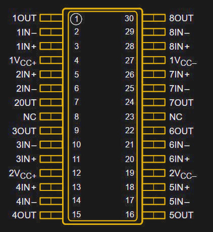
However, the largest number of op amps ever integrated into a single package is eight: until a few years ago you could get yourself an EL5811, a TL084x2, or even an LM324x2, all of which were octal op amps. The same basic circuit in each case was also available as a single, dual or quad version, so the octal op amps were really “dual quads”.
While such a thing might seem useful if you want to squeeze lots of amps in a small space, using two separate quads will give you much more flexibility when it comes to layout and routing of your circuit. We suspect that’s the reason these chips never gained much traction in the market.
Power Consumption
The classic uA741 consumes about 1.7 mA in a typical application. More modern designs have managed to reduce this: for instance, the OPA171 is compatible with the ‘741, has better performance on nearly all measures (bandwidth, slew rate, noise, offset), and uses just under half a mA. Modern circuit design techniques as well as advances in semiconductor manufacturing have enabled a way better performance/power ratio than was possible in the 1960s.
Several manufacturers have introduced op amps in the ultra-low power category, which consume less than one micro-amp. An example is the LPV801, which uses only 450 nano-amps. But the most frugal op amp on the market today is the NJU77000, which draws no more than 290 nA. To put that number into perspective, a typical CR2032 coin cell has a capacity of around 220 mAh, meaning that it could theoretically power an NJU77000 for 86 years — of course, self-discharge will drain the battery long before that. The specs of this op amp are not stellar, especially when it comes to bandwidth: a maximum of 1 kHz is way too low to process anything resembling audio, but is plenty for slow-moving circuits like gas sensors.
Output Current
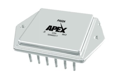
On the other end of the spectrum are power op amps that can drive large currents into a load. The classic L272, which is often used as a motor driver, can deliver a full amp on each of its two channels. But technology has moved on, and today you can buy the beefy PA50 and PA52 from Apex Microtechnology. These massive op amps can output 40 A continuously and 80 A for short periods. And although they come as a single (rather large) component, inside they are not single chips but hybrid modules: a set of integrated circuits and discrete transistors directly bonded onto a common substrate.
All this power comes at a price though; at several hundred dollars a pop, these are not your garden variety op amps. In fact, if you need more current than your preferred amplifier can deliver, it might be a better idea to make an output boost circuit using discrete power transistors. One good text on this topic is application note AN18 by Jim Williams, which demonstrates various ways to increase an op amp’s output current, voltage swing, or both.
Supply Voltage
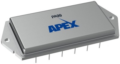
Most op amps from the earlier days could work with pretty large supply voltages: +/- 15 V was normal back in the 1970s. In today’s age of Arduinos and ESP32s, this seems excessive, and indeed many modern op amps will happily work at 3.3 V or even lower. At the other extreme however, op amps that can work at more than 100 V are also reasonably common; the LTC6090 and the ADHV4702 are examples that can work at 140 V and 220 V, respectively. But the real winner in this category is the PA99 from Apex: this op amp will happily work with 2500 V across its supply pins. It can deliver 50 mA on its output and has a gain-bandwidth product of 28 MHz. Like its high-current siblings it’s an expensive chip, at about a thousand dollars, so you’re not likely to find it in any consumer products. The main market for specialized chips like this is scientific instruments and industrial equipment using piezo actuators or electrostatic deflection.
Bandwidth
Speaking about bandwidth, which op amp is the fastest? There’s not actually a single, definitive answer to that. Let’s start by looking at the open-loop frequency response of an op amp: it’s high (more than 100 dB) at low frequencies, all the way down to DC. At some frequency, the gain begins to drop, at what we call the -3 dB point; this is where the gain has reached 70% of its DC value. The gain then continues to drop by 20 dB per decade to reach zero dB at the unity-gain frequency — zero dB means a factor of one.
In practice this means that if you configure the feedback network so that the total amplifier has a gain of one, the bandwidth of this circuit will be the unity-gain frequency. If you set it to a gain of two, it will have half the bandwidth. A gain of ten will result in one tenth the bandwidth, and so on. Since the product of the gain and the bandwidth is always the same, the unity-gain frequency is also called the gain-bandwidth product.
Most general-purpose op amps can be used at any closed-loop gain. But this flexibility comes at a price: the unity-gain frequency has to be kept relatively low to prevent oscillation. For high-speed applications you can therefore buy op amps that have been decompensated. This means that the internal circuits have been adjusted to run at a higher bandwidth, but also that the op amp cannot be used in the unity-gain configuration; the datasheet will specify a minimum closed-loop gain at which the amplifier can be used. If you don’t respect this limit, then your circuit may oscillate.
The graph below shows the open-loop gain-versus-frequency plot of a fully compensated op amp and a decompensated one. Control theory tells us that we will end up with a stable closed-loop system if we close the loop at a point where the open-loop gain drops by 20 dB per decade. (Actually, it’s more complicated than that, but we won’t go into that now.) For the fully compensated op amp this is true at any gain. But for the decompensated op amp, the gain drops by 20 dB per decade only up to a point; this is Gmin, or the minimum gain at which the amplifier will be stable. Note that the bandwidth at this point is much higher than it would have been for the fully compensated amplifier.
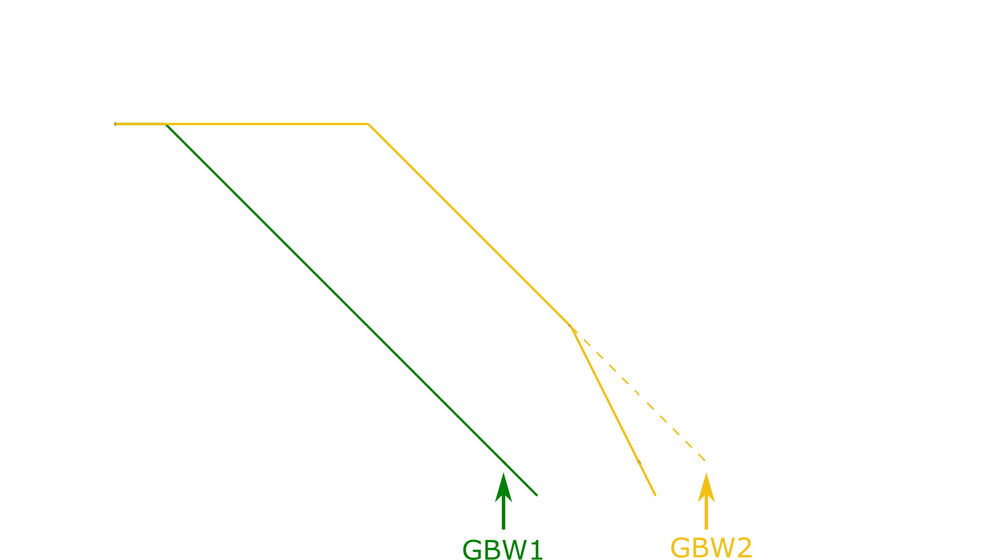
The op amp with the highest gain-bandwidth product you can buy today is the OPA855, at a whopping 8 GHz. However, because it is a decompensated amplifier, you have to use it at a gain of at least seven, in which case it will “only” reach 2.5 GHz. The fastest non-decompensated op amp is the THS4304, which can work in any configuration all the way up to its unity-gain bandwidth of 3 GHz. But before you run off and buy this chip to build a multi-GHz amplifier, remember that proper circuit layout becomes critical at such frequencies; any stray capacitance in the wrong place can upset the loop stability and turn your amplifier into an oscillator.
Slew Rate
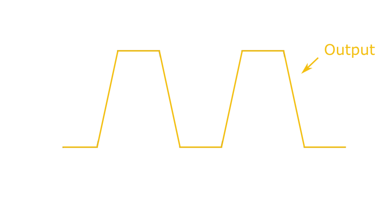
Bandwidth isn’t the only measure of speed though. Another spec that you find in any op amp’s datasheet is its slew rate. Usually measured in Volts per microsecond (V/us), it tells you exactly how quickly the chip’s output voltage can change. A simple way to measure an op amp’s slew rate is to have it output a square wave: the slope of the output’s rising and falling edges will be equal to the slew rate.
The slew rate is largely determined by the internal bias current of an op amp, and is therefore usually proportional to the supply current. Typical values range from 0.5 V/us for the uA741 to 20 V/us for the TL072. Some op amps have a clever trick inside known as slew boosting, where the bias current is temporarily increased when the op amp detects that its output can’t keep up with its input.
The highest slew rates are available in current feedback amplifiers (CFAs), which are similar to op amps in many ways but different enough that we don’t count them as such in this article. Compared to ordinary op amps, they have low open-loop gain, high input offset voltages and bias currents, and cannot be used in all feedback applications. They are commonly used in high-speed circuits where a high slew rate is the most important requirement.
Not surprising then, that the op amps with the highest slew rate combine features of CFAs and regular op amps, somewhat blurring the line between them. For example, the EL5102 has a slew rate of a whopping 3500 V/us, but a meagre 66 dB of open-loop gain where most basic op amps have 100 to 120 dB. Its input bias current is quite large as well, at 2 uA typical. The MIC920 does a bit better, but at 85 dB it’s still not a great op amp. The real winner in this category is the PA107, which can move its output at 3000 V/us but still reaches 140 dB of open loop gain. It also draws about 50 mA from its supply, so it’s not something to use when you’re designing for low power.
Unusual Materials
Nearly all integrated circuits you can buy today use silicon as their base material. A few high-speed circuits, including some of the high-speed op amps mentioned above, are made using silicon-germanium (SiGe), although this is just the top layer of a chip that’s otherwise pure silicon. Potentially, other semiconductors such as gallium arsenide (GaAs), gallium nitride (GaN) or even silicon carbide (SiC) could be used to manufacture op amps; however, given the significant cost difference with ordinary silicon these materials are mainly used for specialized discrete transistors and ultra-high speed integrated circuits.
A few research projects have shown interesting results though: The KTH Royal Institute of Technology, in Sweden, has demonstrated an op amp made in silicon carbide technology that can work at ultra-high temperatures up to 500 °C. Its performance is far from stellar, but its robustness means that it should be able to work in environments as hostile as the surface of Venus.
Here on Earth, silicon is firmly established as the semiconductor of choice, and that’s unlikely to change anytime soon. But as we’ve seen, silicon is flexible enough to enable a huge variety of op amp designs for nearly any imaginable application.


Very interesting. I worked with 741s at school and it’s remarkable to see how far their brothers and sisters have gone.
One small note. Microamps are not abbreviated “uA”, but “μA” – the prefix is the Greek letter mu. Lots of people make this mistake, including the august Big Clive Himself.
My keyboard does not have a mu key. In fact a lot of software also defaultly recognized u as μ.
crtl+alt+m
µ shows up on my nordic keyboard
I can never remember the key combinations, so I google it, and then cut and paste the displayed character σε αυτά που γράφω.
Okay, I know what the solution is. It’s so simple, I don’t have a clue why it’s not just something everybody already does. Some people probably already do. I hope. Right now, I am making a text file, containing nothing but μ in it, and putting it on my desktop. Hold on. Okay, done. Wait, let me add °. Done. Every time I have to look up a symbol, it’s going in the file. If it gets too unwieldy, I’ll organize it into categories. Oh look, it’s growing already! μ°©℗®™Ωπ∞. That takes care of 90% of the characters I’ve looked up multiple times. Dang, I feel like I’ve accomplished something today!
good idea. you can also use those characters in the filename itself, so you don’t really have to put it into the content of the file.
Putting those characters into a “sticky note” on your computer’s Desktop. Great idea BBJ!
On a Mac, it’s option-m => µ
On Windows 10 or 11 press Win+. (dot), a popup opens, switch to symbols, and there is µ and any other symbol
Does that apply to ua709s? Fairchild’s prefix.
Fairchild’s own datasheet calls it a μA709. I would call that definitive.
When I’m lazy (which is usually), I use ‘u’ in place of ‘μ’, because it’s much easier to type, and everybody knows what I mean. An added benefit is that you can tell when you’re dealing with a pedant.
In PSPICE (and I think also SPICE), ‘u’ or ‘U’ suffxes on numbers are both accepted to mean 10^-6, since SPICE is case-insensitive, and since SPICE was around long before Unicode. Also because of this, ‘m’ and ‘M’ mean 10^6, so if you really mean 10^-3, you have to remember to say “MILLI”. I’ve been caught by this more than once.
Actually, at least in LTSpice M and m are milli = 10^-3.
Meg is for Mega = 10^6
http://cds.linear.com/docs/en/software-and-simulation/LTspiceGettingStartedGuide.pdf
Jeez. Did I really get that backwards? Thanks.
“u” is a generally accepted alternative to µ as an input for text fields, for those who don’t have µ on their keyboard layout of choice. (if one does engineering especially electrical engineering, add µ to your keyboard layout if it doesn’t have it…)
But having µ on my own keyboard, it is rather annoying when programs decide not to recognize what it means.
Also, if you make a program that writes out “u” instead of “µ”, then fix your program…
In written articles, it would be nice if people took the time to just go to Wikipedia’s article about “micro” and copy paste the character from there. Like I do with Ω, a character I don’t have on my own keyboard. (though, usually I just write ohm since it is short enough.)
If you care enough you can put & micro; or & omega; in an HTML document and then copy from your browser.
Don’t use spaces after the ampersands though. Hackaday says “Invalid security token” if you write those without the space.
If the mu key was good enough for Aristotle’s laptop; it should be good enough for us!
And where are the Cuneiform keyboards?
B^)
Your small note has now become the biggest issue of take away regarding the subject. What a way to deflect the value of the subject!
So, does a Greek cat say, “μ” “μ” “μ”?
Lots of people don’t know you can type Alt gr + m to get µ. I don’t need to type it a lot, so even i probably don’t remember to use it.
And that was obviously a reply to Someone
HaD’s comments are broken by ad-blockers / NoScript, replies go to the “top” level by default. Very annoying.
Sigh. Of course. Someone games the system, and that just prompts other people to game the game, and then nothing works right, ever again.
Not all keyboard layouts are the same.
So it won’t always print out µ. In a fair few cases it won’t print anything.
One can always change/modify the layout, the physical keyboard is just an array of buttons sending scan codes, what character those codes ends up as is what we call a keyboard layout and this can be altered. So need a special character, then just add it.
I know about layouts, but i would think that µ would be pretty standard. I could be wrong.
µ is pretty standard but where is it. You can use ALT then type a number on the number pad by what number represents µ depends on the installed code page (keyboard layout).
The better way, just because it avoids the code page issue, is to use Unicode. Don’t know how this is done on other platforms, but on MacOS, once you enable Unicode entry, it’s just hold down option key and type the 4-digit hex code, for the whole UTF-16 set. So Option-03BC gives me: μ
Of course, I first have to Google “mu” to get the Unicode code, and at that point I usually just copy/paste the character instead…
I tougth we are hackers and can make an extra keyboard for special caracters!!
As scientist I have to enter/ write these “greek” letters often. On linux I find temp changing into greek keyboard (with shortcut) layout most convenient for that. μ is not on all layouts under “alt gr + m”. as for hint of entering and remembering unicode codes… that is a pure sadism. Try entering all letters with unicode codes, then we will talk.
US keyboards typically don’t have the Alt gr key. And the Ctrl-Alt workaround at least on Windows doesn’t work unless you fiddle with keyboard layout settings.
In Windows type Alt+0181 (hold down Alt, type 0 1 8 1 on numeric keypad, release Alt.) This shortcut is shown in Character Map app–search for “micro”. “U+00B5: Micro Sign” is the first entry and the keyboard shortcut is shown in the lower right corner. You can also just select and copy from Character Map.
And to me, that’s what really, REALLY sucks about Unicode: even when you are using the pixel-for-pixel EXACT copy of a character (or “glyph”, if you insist), you end up with two different names, and two different code points. (i.e., “micro” vs. “mu”.) Oh. Except that since every single font designer gets to determine which characters to include, you never know if U+03BC is going to give you a ‘μ’ or not. Humans (facepalm).
I used to use this Alt type code page access right up including Win XP. Now on Win 10 all the Alt codes are different. Which simply means the default code page is a different code page by number.
Hat down for displaying a good ol’ Yugo 45 as an illustration
Was that a Yugo? I thought it was a Fiat 147.
It is Yugo ❤️
Not a silly mistake as Yugo was based on a version if the Fiat 127.
“The highest slew rates are available in current feedback amplifiers (CFAs), which are similar to op amps in many ways but different enough that we don’t count them as such in this article. Compared to ordinary op amps, they have low open-loop gain, high input offset voltages and bias currents, and cannot be used in all feedback applications. They are commonly used in high-speed circuits where a high slew rate is the most important requirement.”
Current-feedback amps also don’t have their gain and bandwidth linked (gain’s not strictly dependent on bandwidth), hence the reason that high slew rates are available.
And the reason why the gain and bandwidth are linked in op-amps is because they’re designed with a “dominant pole” that slows it down. Otherwise all the different parts of the circuit would behave each according to their own frequency/phase responses and the circuit would go all over the place. Decompensated or non-compensated op-amps don’t have this built-in lowpass filter so it has to be included in the feedback loop if you want to use it at unity gain. The advantage is that you can use a higher order filter than the -20 dB one, but the disadvantage is that you have to build it yourself.
Thermal (offset) drift is probably an important specifications for for those more used to digital than analogue
While not fully generic opamp, Microchip HV257 is a fun kind of extreme: 32 amplifiers in one package, with 300V operating voltage.
Had to look that one up
A 32 channel, 300V sample and hold amp.
“The output of the HV257FG will swing from 0 to 295V. The
internal closed loop gain is set at 72V/V. An input voltage of
4.096V will give an output of 295V. ”
So.. it’s for driving an array of high voltage… somethings…
*Definitely* started as someone’s ASIC.
Possibly an electrostatic printer/plotter. Some operate in that neighborhood, and they have the need for a large number of drivers, since they have start at 100 nibs/inch or so. I used to work on Versatec plotters, in the mid-1980s. Don’t remember what they were driving the pins with, but it may have been that. The printhead was bonded directly to one edge of the driver board, and that had multiplexed inputs, so it did need a sample/hold of some kind.
I’m just amazed that the part works in a QFP package.
If you look at the datasheet, all the HV pinouts are right next to each other down one side of the part
Given a .65mm lead pitch and a reasonable assumption of .3mm wide leads with a .1mm worst-case misalignment, that leaves 0.2mm spacing between pins that could be 300v apart.
That’s a field gradient of 1.5 kV/mm, which, seems like a lot on an otherwise bog standard PC board. If you look at a typical HV part, the lead spacings are usually quite a bit.. more.
SteveS: It probably doesn’t work. Probably, anybody using it at anywhere near its maximum coats the portion of the board that has these signals so close to each other, with a decent dielectric.
Nanoamp to gigahertz ? that is for sure not for imperial system fossils.
Except that there never WERE non-metric units for electrical current or frequency.
Cycles for frequency and then there was the Gaussian system of units for electromagnetism, which included units such as the Franklin for static charge. These were kinda-sorta metric because they were associated with the CGS system, but not with the SI metric system.
And you don’t think it’s a little lame to distinguish between “cycles per second” and “Hertz”, when the conversion factor is exactly 1? Serisously, it’s like Celsius/Centigrade.
“Cycles per second” is a definition, not a unit. “Cycles” (Cy) was used as a unit, such as, “50 kilocycles”.
The metric system doesn’t have a monopoly to the unit time of one second, so you can’t say that every unit which counts in increments of one second are “metric”. The Hertz became the metric unit of frequency only as late as 1960. Before that it was the IEC standard since 1935, while the metric system didn’t have a special named unit for frequency.
“two equal point charges spaced 1 centimetre apart are said to be of 1 franklin each if the electrostatic force between them is 1 dyne.”
And from the definition of charge, you get the definition of current, for which they didn’t yet have a name, so the unit for Franklins per second is anachronistically referred to as a “statampere”. For other definitions, you had the Biot from Jean-Baptiste Biot, which is about 10 Amperes.
These were “metric” in the sense that they used the CGS system to define them, but the metric system itself wasn’t quite defined back then so it was a hodge podge of different standards and definitions. For example, Gauss chose to use millimetre, milligram and second as the base units, so his units were of different magnitude from the rest. The Metre, Kilogram, Second system that we know of as the “metric system” or SI didn’t come to use until the mid 20th century.
And for the very earliest “units” of electric current, there was the one guy who measured static charges by how far up his arm it hurt to touch the Leyden jar.
Now one might start to wonder what the drift and accuracy of “how far up one’s arm it hurts when holding across a differential voltage.” is in practice. My own guess is that any random 1N4007 would serve as a more stable and accurate reference if considered to be 0.6 volts when having “about” 10 mA flowing through it.
The charges that they generated with Wimshurst machines and other crazy contraptions would have blown common 1N4007 diodes instantly.
Back when I worked on minicomputers, I was resting my finger on the inside of one of the flanges on a reel of 1/2″ magtape, while waiting for the tape to rewind. I then touched the frame and got a hell of a ZAP. So I got curious and tried this again, but this time I wanted to see how much voltage it had generated, so I touched the tip of a probe on my Fluke 77, which had the other probe grounded. Blew the input of the meter. Idiot.
I weren’t thinking that the 1N4007 would replace the arm.
But rather the accuracy and stability of “this feels to be about this much voltage” and a diode that we know is about 0.6 volts if we let roughly 10mA flow through it.
Of course our diode would need other circuitry around it to serve as a volt meter.
Not that a 1N4007 has any reputation for being an accurate and low drift voltage reference. But my guess is that it would be a better reference than the typical arm.
Not to mention that diodes weren’t invented until the 20th century.
Hence why the standard used was the Voltaic Pile. Currents were measured using compass needles, and varying resistance networks to compare currents by their effects on the compass needle.
That evolved into needle galvanometers, which are pretty much what we used for multi-meters up until the digital revolution.
Wait: so you’re telling me that the one set of standards to rule them all was a hodge-podge of different things?
heavens.
Yep. There’s no neat way to derive all the basic units from the fundamental ones without someone getting the short stick and having to deal with stuff that’s ridiculously small or way too big, so the units were first chosen by however anyone wanted to use them and they didn’t match at all. Converting the math between domains was an exercise in futility because you had to convert all the units to the same magnitude. After all, if you’re measuring areas in square centimeters and length in meters, the units don’t cancel out correctly – but all that was hidden behind an abstract unit which didn’t say what it was.
So, they unified the whole thing and dictated quite arbitrarily that everyone should use CGS, but that apparently wasn’t good enough so they changed it again to the MKS system, to the delight of all the engineers who now have to deal with units of pressure and stress that, practically speaking, measure the weight of an apple spread over an area the size of a coffee table. Meanwhile, the relevant areas, moments of inertia, etc. are measured in millimeters to the power of 1, 2, 3, 4 or 5, so that every calculation result is a million billion trillion something divided by trillion billion million, or was that billion million trillion? How many zeroes? Don’t get the magnitude wrong! Nothing as simple and relevant as pounds per square inch for example.
And so we ended up with the System International (SI), which is written in reverse order because of the French.
NONE of the SI units are based on even numbers, today. Since the original standards have been replaced by standards that yield greater precision and repeatability, we get things like the meter, which was originally one ten-millionth of the distance from the North Pole to the equator, on the meridian that goes through the center of Paris, is now the length of the path traveled by light in a vacuum during a time interval of 1/299,792,458 of a second. And a second is the time duration of 9,192,631,770 periods of the radiation corresponding to the transition between the two hyperfine levels of the fundamental unperturbed ground-state of the caesium-133 atom. So any notion that the SI units are based on natural quantities is obsolete.
People lacking a sense of “how big is it?” and “does this number even make sense?” is a real problem in civil engineering btw. I’ve seen buildings collapse, and I just recently saw an engineering company do an “oopsie” by miscalculating the wind loading factor of a small suspension bridge by a factor of 10.
If you say “This rope material holds 500 pounds per square inch”, that’s something concrete and tangible. You can hoist up to 500 pounds on a rope that’s little more than an inch thick. That’s a real tangible scale. If you say it holds 3.45 Megapascals, what does that even mean?
“There’s no neat way to derive all the basic units from the fundamental ones without someone getting the short stick and having to deal with stuff that’s ridiculously small or way too big,”
No, that’s not quite it. It certainly wasn’t “arbitrary” or “not quite good enough.” The issue isn’t the derived units: it’s the *equations* that people used.
The problem is that in the 19th century they hadn’t quite figured out all the connections between electromagnetism and mechanics. Ampere’s law was brand new. Conservation of energy was brand new – Helmholtz and Grove published it in the mid-1800s. Hell, the term “energy” didn’t exist until the turn of the 19th century!
So instead, you had this idea of “mechanical force/energy,” and “thermal heat,” and “electrical power.” Mechanical energy and force got measured in ergs and dynes. Thermal heat got measured in calories. Electrical power got measured in watts.
But by the turn of the 20th century it was well established these were all the same thing and that the concept of energy was fundamental. So you wanted to have all of those things be identical. The thermal part’s easy, there are no ‘extra units’ involved there.
The electrical part is what sucked. That’s where you needed to jump through hoops to try to keep things simple. And the reason why you shifted from CGS to MKS is just because ain’t no way in hell the scientists were going to get engineers to change.
‘If you say “This rope material holds 500 pounds per square inch”, that’s something concrete and tangible.’
That really depends on where you live. For me, the pounds per square inch is utterly meaningless. Pascals (Newton per square meter) I can relate to.
>That really depends on where you live. For me, the pounds per square inch is utterly meaningless. Pascals (Newton per square meter) I can relate to.
That wasn’t the point. You know Newtons and meters like someone knows inches and pounds – it’s the unit magnitude that is the problem here.
One Pascal is such an incredibly tiny amount that it relates to nothing. It’s like going to the store and buying meat in micrograms. You wouldn’t know the difference, and instead of having one scale that spans the familiar range of things, you get multiple: hectopascal, kilopascal, megapascal… that’s a range of about 0.0145 to 145 PSI. If you say there’s 60 PSI in your bicycle tire, you can instantly tell whether it’s a little or a lot because 1 PSI is little and a 100 is a lot, in human terms, and you don’t have to change magnitudes. You want to compare to a scuba tank – that’s 4,000 PSI and that’s really a lot. With the metric system you switch from measuring in kPa for the bicycle to MPa for the scuba tank, and that confuses people. First you have 400 kPA and then you have 27 MPa – what? Why? It’s like the two things have no relation. Of course we know the correct answer, but it’s still silly and most importantly it’s not painfully obvious for what’s happening – especially when you’re doing the math and you get the answer as expected, yet you miss the unit error in the middle and don’t realize you’ve accidentally switched from one size scale to the next because your error masks the difference.
Think of it like this: when you’re driving a car, you can easily know your speed by the engine sound without looking at the meter. If someone came in and started switching gears, all of a sudden you lose your reference point and you can’t hear it anymore.You have to start taking your eyes off the road to check the meter.
Also, the reason why metric countries still use “bar” which isn’t a SI unit, is because there is no convenient magnitude between kPa and MPa. It’s a factor of a 1,000 sized gap that’s missing one more step in between right where people would need it the most. The bar is a deprecated unit that officially should not be used, but we can’t get rid of it because it’s useful.
Also, metric countries should be using cubic decimeters and cubic centimeters instead of liters and milliliters, and things like deciliters shouldn’t even exist. Strictly speaking volumes should be measured in cubic meters to make the math rational, but for everyday matters it would be a pain in the butt so they just let you use non-SI units again so there would be agreement at least on that. Every country has their own convenience units anyways.
“but the metric system itself wasn’t quite defined back then so it was a hodge podge of different standards and definitions.”
In fact, the ampere is the *reason* why that hodgepodge went away, and the reason why we’ve got the goofy mixed system (MKS instead of MGS) we have.
It doesn’t matter what set of derived units you use for basic dynamics. Your base unit of force could be a meter-gram/s^2, unit of energy could be a gram-meter^2/second^2. It all works out the same. The reason is because there’s no ‘outside’ unit of energy. All the energy in dynamics comes from forces and distances.
But the problem comes when you add *electricity* to the mix, and you want to keep all of the simple, nice, electricity formulas everyone here is used to, such as power = voltage*current =force*distance. With no proportionality. By the time people understood enough about the physical world to build up real systems of units, “power = voltage*current = force*distance” and the like were already super-entrenched in engineering. No way in hell were they going to get them to change it.
The problem was that physicists really liked Ampere’s force law being a simple proportionality with no constant. Two wires, force per length is twice squared current per unit length away from it (twice cuz there’s two wires). And you can’t *have* both of those proportionalities unless your units are super-weird.
So instead, the engineers won, physicists had to switch to a new unit of force (which became the newton, which is an *incredibly* young unit!) and use the electrician’s units for energy (watt, watt-second which became joule). The physicists weren’t entirely screwed, though – because while Ampere’s law now needed a constant, it was a rational constant (10^-7), which corrects the mismatch (it’s the sum of the base unit exponents in the unit of energy).
Of course the funny thing is that just a few years ago, when they redid the metric system, they actually completed the destruction of the ‘rational unitologists’ by defining the amp in terms of number of electrons.
Theoretical physics and theoretical electrical engineering won, but civil engineering and practical electrical engineering lost. The latter is still done using a hodge-podge of weird convenience units and US customary units mixed with SI units, and civil engineering got complicated enough dealing with the astronomically small and large unit magnitudes (in the same calculation) that people just trust the CAD program and hope for the best.
Although, the physicists and engineers couldn’t really keep to the metric system in any strict form and had to invent their own “inches and pounds” by introducing convenience units like the Angstrom, electron-Volt, light-year, parsec, Jansky… and my favorite one the Barn – which is approximately the size of an Uranium nucleus, said to be “as big as a barn” in comparison to other elements.
Another one is the “shake” which is defined as 10^-8 seconds.
Then for lubricating oils, we’re still using “centistoke” which is a CGS unit.
You’re forgetting the funniest “convenience unit”; the Smoot. (equal to 1.70 metres)
You think practical electrical engineering lost?!?
You’ve used Ohm’s law, right? And Q=CV? And P=VI? And OK, you might not have used the fact that radiated electromagnetism can be thought of as a 377 ohm impedance, but that’s super-convenient too.
The reason there are no random constants stuck in there is *because* of the rationalized MKS system. There’s absolutely no reason all of those constants had to be unity (and no reason that free space had to be thought of as having an ‘impedance’).
The fact that a “practical” engineer doesn’t have to think about whether the “power” in those equations is electrical, thermal, or mechanical power is just a massive benefit.
“a hodge-podge of weird convenience units and US customary units”
Every field uses convenience units. Air pressure is measured in atmospheres, hectopascals, millimeters of mercury, millibars, and torr. Distances are measured in meters, kilometers, microns, Angstroms, light years, AU, and megaparsecs. Time is measured in nanoseconds, seconds, minutes, hours, days, and ticks of a clock.
Getting rid of convenience units would be insane. The key was to make sure the system of units is coherent, so the *equations* stay the same. Otherwise you end up with “electrical power” and “mechanical power” and “thermal power” and you can’t just set equations equal to each other.
Jeez, it’s practical engineers who *come up* with the convenience units in the first place. It wasn’t a theoretician who decided racks should be 482.6 mm wide, vertical spacings should be measured in units of 44.45 mm and horizontal spacings should be defined in units of 5.08 mm.
You could make a pretty good argument that the entire world of electrical units is actually inverted.
Since the electrons move from negative to positive, the Ampere, at least, should be negative. But, then what does the volt actually measure? if it’s the preponderance of electrons (remember, *elec*tricity, and all ) then what we consider the negative pole should rightly be a positive value, which would at least eliminate the nightmare of having a negative sign in Every Single Equation.
@[SteveS]
I like it how it is. The electrons stay still and pass the rest of the atom back and forth.
>Getting rid of convenience units would be insane.
Precisely – and that’s why all the brouhaha about the metric system is insane. It’s trying to shoehorn everything into this neat little box that’s so smart and elegant, yet at every turn you have to admit that what the people really need is pounds and inches – not prefixes.
There is no direct conversion between “thermal power” and “mechanical power” anyways once you get to the real practical engineering. Everything has conversion factors and equations to fit things together because the ideal representations exist only on paper. Once you write down how it “should” work in the neat elegant rational math, you then turn on the FEM analysis software and throw the analytical solution out of the window because it’s too simple and not relevant to the real world.
“Precisely – and that’s why all the brouhaha about the metric system is insane. It’s trying to shoehorn everything into this neat little box that’s so smart and elegant,”
The advantage of the metric system has nothing to do with prefixes. That’s just crap that’s propped up over the years for some bizarre reason. The point of the metric system is to have as few base references as possible that are easily repeatable, so that there’s as little drift due to reference variation. It’s to have *definitions*.
That’s why it’s silly to say the US isn’t metric. Of course the US is metric. All US standards are based off of metric units. All weights in the US are referenced to metric weights at NIST. The friggin’ definition of the meter itself comes from NIST measurements.
“Once you write down how it “should” work in the neat elegant rational math,”
There is no single “neat elegant rational math.” You can’t go back to the 19th century, find measurements in volts, statcoulombs, and abfarads and just convert them in your spreadsheet. It *doesn’t work*. The equations are *different.*
Before you can *have* your ‘neat elegant rational math’, you have to agree what all of these arbitrary units mean, and those define the equations. If all of the units seem silly and pointless, that’s because SI *did its job*.
The math isn’t real. Only the results of an experiment are, and you can’t just say “oh, I’ve got a potential of X volts,” and that’s good enough – because not only is a volt arbitrary, the entire concept of “potential” is arbitrary.
TI sells some precision amplifiers with single digit fA input bias currents. fA currents are 10^-15 Amps. You are close to counting thousands of electrons per second at that point.
Yup like the LMC662. In practice, the input offset and bias current is sub fA and limited by circuit layout more than the chip. Super hard to verify that during production so they don’t advertise it in the datasheet. search for the Bob Peese App note “what’s all this femto amp stuff anyway”
What a pleasure to see a Jim Williams app note referenced in the text. When he passed, and Robert Pease a few days later, the analog world lost two giants the likes of whom we will never see again.
Bob Pease once took me out to the woodshed for something I had posted online.
It still smarts a bit when I sit.
I wish I had saved our exchange.
I miss him.
I locked eyes with Bob Pease from 30 or 40 feet at a trade show in San Francisco once, many years ago. I think he knew I was an avid reader of his columns. Wish I’d gone up to him to say hello, but I was a bit shy then.
We live in a wonderful time when you can obtain a small hedaphone amplifier or pre amplifier with exceptional performance for a little money. Al do their is a little sense in switching OP Amp’s (as designs become quite good for a long time now) those who enjoy in such have a nice time doing it.
I don’t approve you putting the Yugo in front for the article. There ware better things for that like for example:
https://www.edn.com/wp-content/uploads/media-1123856-widlar-salute2-thumb.jpg
Have a nice time and happy Easter to those who celebrate today.
listen here you little-
It’s a wonderful time in a lot of ways there are so many prototyping modules / breakout boards and micro-controllers that handle complex protocols at hardware level, that glue logic is just a bunch jumper wires and code is just stringing together a bunch of libraries. Even with bit banging a protocol – well there’s a library for that too.
BUT! If you truly have a challenge and you need to jump outside the box and design your own sensors as something suitable isn’t available then things like op-amps become your magic tools for real world sensors.
Give me a bag of 7400s, NE555s, LM309s, 2N2222s, 2N3055s, LM741s, and some LEDs
and I can move the world.
I would replace that 741 with something a little better – the 741 has a terrible crossover glitch when it goes from supplying current to sinking it. This makes it completely unsuitable for audio work.
Now days you can get op-amps with pA input offset (yes pico) and nV/°C thermal drift. Way past just an audio amp , exceptionally high accuracy instrumentation amps.
something i was surprised to learn is that an op amp and a comparator are the same thing. and now i wish this article had explained to me why that isn’t true :)
A comparator is a sub-set of the op-amp’s capabilities. If you force the output of an op-amp to two logic states, it’s a comparator. Make sense?
Except an op-amp makes a very poor comparator. Recovery from saturation takes a very long time in an op-amp.
That is correct. Op-amps are designed to operate closed-loop, where the inverting and non-inverting inputs are at very close to the same potential. They don’t necessarily work well, or even as you would expect, when there is a large difference between the two. And by “large”, I mean that even one volt is a large difference. By comparison, comparators are designed to give the correct output for any combination of inputs within the prescribed range.
A compartuator has an open ended output, that is, they are designed to either source or sink current on the output but not both so they are not symmetrical.
They also don’t have closed loop feedback to limit the gain so there are not an AC signal amplifier.
Also when you drive an (output) transistor “hard” on you have a challenge trying to turn it back off quickly. Compartuators have extra circuitry to deal with this problem but op-amps don’t have this extra circuitry because you shouldn’t drive the output of an op-amp “hard” on in either direction.
Tomuto, tomµto, the important thing here is the author, Robin Keary, has done a very good service and nice job of laying out how far op-amps have come! Let’s get back on track?
The only area I see that needs an addendum is the ‘Supply Voltage’ section, which imo, should mention the 0-5V (unipolar! horray for Arduino!) ones out today. One example I Googled is the onsemi LM358, TI’s TLC080 family, and probably quite a few more.
‘Back in the day’, you had to futz with a +/- 15-ish volt power supply, which is now officially a PITA. ;-)
Personally, I have a hobby interest in returning to some analog stuff, super fun, and have a tube of TL084’s here waiting for a rainy day.
It has always been up to the designer of a circuit to choose supply voltages. The datasheet gives +/- 15V as the supply voltages at which the specifications are guaranteed, but you can run any op-amp on a single supply, as long as you ensure that the inputs are within limits measured with respect to V+ and V-. Most op-amps will run just fine at considerably lower voltages than that 30V difference. So this isn’t something that Arduino brought into the world. In fact, DACs and ADCs have long been running on single supplies, with this often having been a selling point, like back into the 1980s at least.
I once got a small assortment of ICs, and some of them were uA702s. I thiught exotic, until I looked them up. Opamps earlier than the 709. My vague memory says it had a separate ground lead. But never anything later.
As I recall, “single rail” was more about internal design. The output could get closer to the + and – rails, which was really useful if you were wanted to run iff 5 or 12 vokts rather than +-5 or 12 volts. When the 324 came out, I remember “it doesn’t need a bipolar supply”, but in fact, running off single polarity was identical to using a 741 that way, set the input to half the supply.
It’s been a long time since an op-amp chip has had all three (+) (-) and (GND) pins.
You can just use another op-amp to create a phantom ground unless the output has a significant loading.
If the output has a high load like a high powered AB audio amp then they still use a split supply anyway.
But yes, as you say, most of the older op-amp were +/- 15V to 18V spit rail or 30V to 36V single rail.
Now there are may op-amps that are 5V or +/-2.5V if you want to put it that way.
Even some for 3v3 but not may as you only have room for a couple of Vbe junctions at that voltage so it’ll be relatively poor function.
Question for all the OpAmp experts out here – is there a low cost OpAmp that can be used as an output for protection of an Rpi or 3.3V Arduino output/ to drive a 12v load at say 1-5A? or measure a 12v input and translate it to 3.3v to read as an input? I know probably should use a opto-coupler but seems there must be a real low component/simple solution in this world (admittedly I am an op-amp naive /total newbie)..TIA
Connect one transistor to the output of the Arduino, and you can have 12 volt output. As for the input, you just need voltage divider made up of 2 resistors.
Can you recommend a transistor that would saturate at Rpi /Arduino 3.3 output drive levels (i.e. LOW)? Thx.
Almost all should, and if they won’t, decrease transistor base resistor value until it does. Start from several kiloOhms and go down to few hundred if necessary.
Maybe –
BD649 / DB651
Darlington Si BJT
Or look for a FET
HFE is more of a problem with a non-darlinton
The LM10 spec claims a minimum supply voltage of 1.1 volts. Is there anything lower?
The Maxim (Analog Devices now) MAX40108 claims to be happy down to 0.9V.
The usual distributors’ parametric searches return some down to 0.65V
I guess if you really want to run your device off a LR44 or a AAA alkaline these things have a use, but in this age of ubiquitous CR2032s it’s hard to think of a use case for them. What did you have in mind?
Thanks. No present use, just curiosity and a desire to fill out the extremes of an extreme opamp article.
I think the LMC 662 is missing in the wonderful article. It´s a quite affordable (<10$) and still in production part that typically has few femto(!)amperes of bias current.
If you connect it free-air to e.g. a 100pf cap as a follower you don't see the output voltage change with a 4.5-digit DMM. It´s fantastic for all kind of super-low-current detectors and experiments.