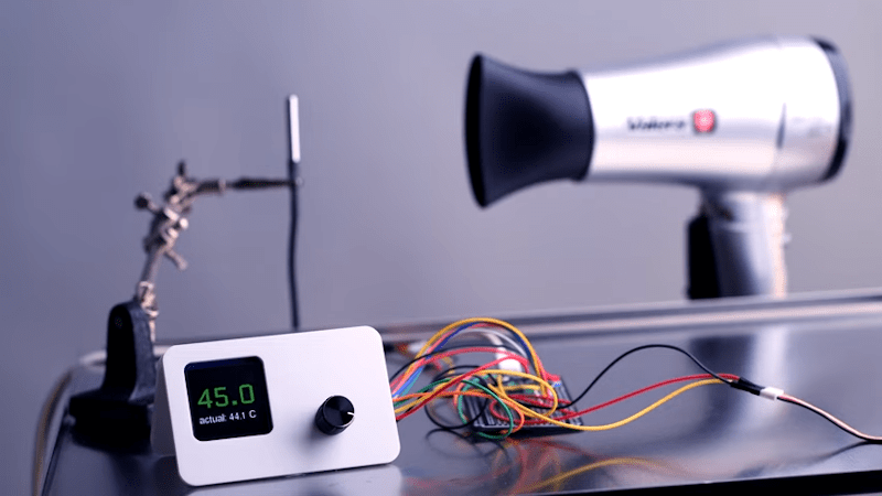
If you wanted to, say, control a temperature you might think you could just turn on a heater until you reach the desired temperature and then turn the heater off. That sort of works, but it is suboptimal — you’ll tend to overshoot the goal and then as the system cools down, you’ll have to catch up and the result is often a system that oscillates around the desired value but never really settles on the correct temperature. To solve that, you can use a PID — proportional integral derivative — loop and that’s what [veebch] has done with a Rasberry Pi PICO and Micropython.
The idea is to control an output signal based on the amount of difference between the actual temperature and the desired temperature (the proportional error). In addition, the amount is adjusted based on the long term error (integral) and any short term change (the derivative). You can also see a video about using the control loop to make a better sous vide burger, below.
PIDs are useful for things other than temperature control, of course. They generally apply to any (usually linear) process where a control value influences some other value. For example, we’ve seen robots use PIDs to follow a line. Some use them for balance, too, or you can balance a ball.


If you really want to do it nicely (with resistive loads only) grab a PID controller with a 4-20mA output and a phase controller (like this: https://www.aliexpress.com/item/1005001632554726.html?spm=a2g0o.9042311.0.0.356f4c4deR7VHP). You’ll get an ultra-smooth process variable
You can use the Arduino IDE to program a Pi pico. And you can use the Arduino PID Library with it.
Hopefully we don’t get any more stuff like that here!
Nowadays I know about this stuff, but it is content like this that got me interested in controls
Neither of those things happened here… so I guess your wish is coming true?
A basic PID controller is literally one line of code (Unless you want it to be readable :-)
That said, there might be value in a Hackaday article about PID itself for the benefit of those who either do not know about it, or who think it is complicated. Most descriptions get bogged down in control theory and calculus.
And then you can get into systems with precontrol and gains that vary with process and environmental variables.
(As soon as this post is sent, I will be off to sit in a car, in a very big fridge, to play with my PID gains.)
https://www.youtube.com/watch?v=qKy98Cbcltw
How about a simple explanation as to how it works then?
Thanks for this!
If you look at the code linked in the project creator’s github you’ll see that the PID controller is literally one line.
Yes, one line, if you ignore the multiple lines calculating the intermediate values.
Nice, another example of using way overkill hardware for very simple tasks.
And how much is it the price is for at Pico?
Haha. I know some people who are basing a whole start-up around thinking that PID control is hard. This is at least a short, simple and finished project that works, without wasting vast amounts of time and money.
However. Burgers, in my burger bobbling view, should be BBQ’d or at least grilled well.
Can we use PID in crypto trading?
What process variable would you be looking to control?
People who don’t PID think the hard part of PID is writing it. Ironically its usually “import someone elses library and link it in and hope it works”
People who DO PID know the hard part is testing it and not building an oscillator.
The hardest part is not unwittingly selling an oscillator…
Yep, the implementation itself is stupid simple, just some basic math. What few rarely explain in a way that is easily digestible is the tuning process. When I first started learning control theory in college after going through pages of text explaining the math, I point blank asked my professor how do I tune a controller for a system that I don’t have/cant calculate a nice perfect plant model for. The response I got was very unsatisfying to me, basically came down to: pick reasonable gains, test and tune till it works. But that’s the way the world is, too many variables and complexity to account for so the best you can do is calculate or intuit the starting gains and iterate from there.
If you had a perfect plan model you would use that instead….
The very fact that you are using a PID rather implies that you don’t fully control and/or understand the system.
A large part of my job is tuning the PID controller that handles the idle control for vehicles sold by a major vehicle manufacturer. And, it really is a case of “ooh, that’s too much. hmmm that’s not enough”.
In this case there is one each of P I and D gains for each gear. And each of those is an 8×8 map that takes controller error and engine temperature as axes. So there is scope for a lot of tweaking and subtlety.
Which is why it takes weeks of work to tune and test.
True, if I had the plant model and the processing power I’d probably opt for a MPC controller instead (model predictive control, basically calculate all possible internal states of the system and select the best one for each sample period). I just meant that even with PID, having a plant model to design the controller off of allows you to really easily optimize control response and know from a mathematical standpoint the characteristics of the controller and plant working together. But like I said the world very rarely works so simply, only the simplest of systems can easily be fully modeled.
Finding a copy of David St. Clair’s “Controller Tuning and Control Loop Performance: PID Without the Math” can save you a lot of confusion/wheel reinvention as it has for me.
i had this dream a decade ago of building a model airplane control system that is based on a gyroscope-accelerometer unit, a microcontroller, and a bunch of black box control systems. the user input would not be translated into control surface positions but rather into a desired movement profile. and it would be up to the microcontroller to feedback-regulate all the control surfaces. so in the extreme version of this where everything is really black boxes, it wouldn’t even know which control signal moves which control surface, it would have to intuit somehow whether it’s ailerons or rudder, for example.
but you could imagine baby steps in that direction where it does have an idea at the beginning of operation but it continually refines it, so it can adjust for coupling factors (ailerons cause adverse yaw, motor causes pitch and torque roll, battery state affects motor, etc). heck, you could even imagine it countering rudder-roll for true flat-yaw behavior (probably undesirable but interesting, right?).
back when i had time for such a project, i couldn’t get a handle on any part of it. i hadn’t even heard of PID, i was vainly trying to reinvent everything. but now that i know a little bit about PID and PID auto-tune, my mind keeps going back to this pipe dream. of course now i can’t hardly get 20 hours of fun project time in a whole year. sigh.
Seems to me exactly how a neural network works!
The PID algorithm is one of my favorite concepts, and is a perfect fit for analog electronics, which I also enjoy (I recall reading recently that digital PID implementations struggle to keep up with their analog counterparts in high speed applications).
In a long lost age (when I had free time) I dabbled in holography. The apex of my accomplishments was a fringe locker circuit which would adjust the length of the reference beam by moving a mirror attached to a tiny speaker (from Radio Shack!!) Two photodiodes were mounted in close proximity and positioned in an area where portions of the object and reference beams overlapped and formed fringes. The difference between their output became the error signal, which was PIDed and fed to the speaker coil. I had pots for each of the forms of feedback, and once I got it working I spent hours twiddling knobs, thumping the table and watching the fringes snap into position. It was so entertaining that for quite a while I didn’t bother making holograms :)
One of Bob Pease’s “What’s with all this ______ stuff, anyhow?” columns tackles PID, and helped me understand the practical side of building the circuit.