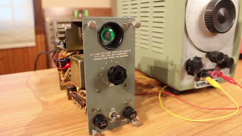
There’s an unknown piece of military electronic gear being investigated over on [Usagi Electric]’s YouTube channel (see video below the break). The few markings and labels on the box aren’t terribly helpful, but along with the construction and parts, seem to identify it as relating to the US Navy from the WWII era. Its central feature is a seeing-eye tube and an adjustment knob. [David] does a bit of reverse engineering on the circuit, and is able to fire it up and get it working, magic eye squinting and all.
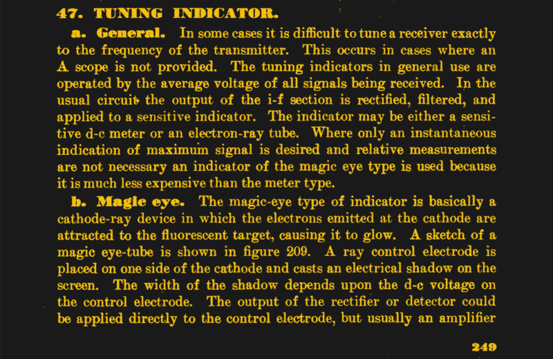
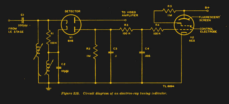
But there’s still the unanswered question, what was this thing supposed to do? Besides power, it only has one input signal. There are no outputs, except the “data” presented visually by the magic eye tube. Commenters have suggested it was used with sonar equipment, calibration tool, RTTY tuning aid, light exposure meter, etc. But if you dust off your copy of Navships 900,017 “Radar Systems Fundamentals” from 1944 and turn to page 249, there’s a section entitled Tuning Indicator that describes this circuit, almost.
This suggests these magic eyes were simply being used as a sensitive voltmeter since they were much less expensive than a mechanical meter. Even if this is the function of the box, there is still the mystery of what it was tuning. Share your thoughts on this in the comments below, especially if you have seen one in the wild.


hal with assistent like mycroft ;-)
Remember them for tuning RTTY in the 60s as a radioman in the Coast Guard.
Small oscilloscopes, like 1 inch, were often used for RTTY tuning indicators. Because there are two inputs, vertical and horizontal, you get signals from both the mark and space detectors.
All you get with most magic eye tubes is one axis. And while I’ve seen various schemes for RTTY tuning in ham radio, I don’t recall magic eye tubes. Since magic eye tubes are cheaper and simpler, I can’t imagine using something better unless it was needed.
Don’t forget, the actual display is like the screen of a scope.
When I was lerning to fly in the late fifties we had indicators that looked exactly like that for indicating the position of the aircraft relative to a vor transmitter. They were passive in that they were receivers only. VOR was very new and had several ways to indicate position from a vor station.
Also was signals…kinda reminds me of a weekstone bridge…used to Ballance visual indicators
So, I joined the navy in 1989, my 1st ship was rather antiquated both physically and communications wise, I was assigned onboard as an electronics tech, I believe what you have is the early version of a AN/URA-17 (if my memory still works) it indeed was used for TTY (teletype) in the HF band…..properly connected to a receiver you used it to fine tune the mark/space so the teletype would work ……properly tuned in frequency it would display a mark line on top and space on bottom with the transition between as hour glass style lines flickering between top and bottom, the mark and space solid lines had to be centered and of the same length left to right as well as centered in the tube read out…..all the old transmitters and recivers shipboard had a 10mhz crystal oscillator they used as a frequency reference, the problem came from atmospherics, Doppler shift, and boats without solid references so the ura-17 gave you a visual reference to tune by, but any et or radioman worth his salt could do it by ear better
Looking at the manual that isn’t the same front panel as a URA-17 (and indeed the schematics are quite different) but that led me to this treasure trove of scanned manuals:
https://www.navy-radio.com/manuals/
Maybe it’s hidden somewhere amongst that lot?
Just give me
a moment15 years and I go find it.My grandpa started his 30+ year Navy career as a radioman. When I was about 8 or so (1988) he showed me one of these he had in his real radio shack full of HAM gear in his back yard. I can’t recall the details of the conversation now but I was captivated by that wonderful green glow. Thanks for bringing up some good memories.
I think it’s a locks water level signal
Null detector. Useful for various comparisons in measurement bridges.
My guess would be nothing less but “the most important device in the universe” (ref. https://hackaday.com/2021/09/23/the-most-important-device-in-the-universe-is-powered-by-a-555-timer/)
I had an old Zenith console radio with a magic eye in the dial for tuning. Very cool bit of old tech.
Yeah, I came to say this too. It featured two green bars that merged in the center when you had optimally tuned the radio to your desired station. It didn’t feature an eye-cup like this did, but I’m sure in a low-light operating environment, that might have been helpful.
Disclaimer: I have no experience with this type of equipment, the US Navy, nor much experience with electronics of the era.
I wouldn’t be terribly surprised if it was a one-off device built along with a larger installation. Whether the larger device was a prototype, a custom installation, or a retrofit isn’t clear.
It’s a MacGuffin… See the briefcase in Ronin; or even more similar, my favorite: the electronic device in Desmond Bagley’s novel Running Blind
https://en.wikipedia.org/wiki/Running_Blind_(Bagley_novel)
Amazing to thing that all that could at one time be built for less money than a mechanical V/U meter!
Don’t believe the other comments.
This thing is a reptilian detector.
OP, go to a hotel for a few weeks, don’t register under your true name.
What about a display for one of those early radio-location systems?
Do these come in red? Because it’s be an awesome eye of Sauron.
Time dialation tuning device for the Philadelphia Project yeah?
For “a long time” meters were expensive, and insensitive. So I think that’s the rise of magic eye tubes, which of course weren’t just a display, but a tube with amplification. I don’t know when tye shift began, in some applications they were used into the sixties. There were meters in WWII military equipment, so I assume cost was a factor. Or rather, magic eye tubes used unless precise readings needed. Command Set transmitters had a magic eye tube, used in conjunction with a crystal to set the variable oscillator to a specific frequency. So you’re looking for a peak, rather than a specific value.
In a military situation you might have to pack this stuff away because your position is being bombed. A mechanical moving coil meter isn’t survive this “packing up” situation.
The eye tubes had a rubber grommet on the front panel holding the tube into the socket. The other tubes (or valves) had a springs and a wire frame holding them in place.
For us older Ham Radio guys these magic eyes were indeed used to tune radio transmitters to tune a crystal to a specific frequency. A company called Gonset utilized this matching on their Gonset Communicator I and II series radios. These were designed for the military and then later used by Ham Radio operators. I know as I have a number of Gonset radios. Gonset later moved to a RF meter on their Communicator III. One must remember the times, During the 1940 radio was still in its relative infantry and various manufacturers had different ways to skin a cat. While I’m not familiar with this particular piece of equipment but familiar with military electronics as I purchased electronics for military applications for 35 years, I can a respond to a number of previous comments the first being that this unit was over engineered. The environment that this particular piece of equipment was to perform is likely lost to time. As with all military equipment you never could be sure if this was intended to be on a ship or maybe in a communication facility in the Antarctic hence the wiring and the conformal coat. You can be pretty sure this type time was not only used by the navy, but likely for other services as well. Keep in mind this equipment was designed well before the common use of transistors and multi layered PC boards. Heat was a factor, I believe based on my experience this item was designed before competent meters were available for this application. Also keep in mind that in the military world you don’t want to have much variation. Although we are only talking a meter here, remember that the radio techs had to deal with. It is far easier to change a tube, than replace a sensitive meter. At the time before mini connectors everything was soldered in place. Imagine some poor tech our on a battlefield looking for some place to plug in his soldering iron. Finally I had a problem with the Utube video toward the end so I did not see where the connector on the rear was discussed, but looking at the rather large connector shell, I believe the input and output were nested in this one connector. One single mating connector to another piece of equipment was standard in the day. As it still is today.
I have some clues but first – perhaps it was a April fools day joke.
Ok, The circuit is actually a split rail circuits ie 0 Volts, A positive voltage and a negative voltage. The 0 Volt rail is generated by the two series capacitors that have an ground in the middle. The output of the rectifier is not DC, it is rectified AC. If the DC voltage of the ground shifts away from 0 volts then there is AC across the two capacitors mentioned. It appears to be designed for a balance AC power input (120V).
So the ground reference is a fairly low impedance at least when compared to the input impedance of the incoming signal.
All of this is important to understand before the next point.
The input is capacitor coupled to a pot and a wiper on the pot goes to the input of a tube BUT and here’s the important point – instead of the other side of the pot going to 0 volts or the reference for the input, it goes to the negative rail !
The pot could instead have been put across the input to 0Volts then capacitively coupled to the tube.
This is making some “magic ratio” between the AC content of the input and the DC content of the input.
This magic ratio is being set by the 3.3k and 22k resistors on the cathode and anode (respectively) on the first tube along with the specific characteristics (VI curve) of the tube itself.
So I am guessing it’s something that inserted into an existing circuit so that you can determine what gain should be used at some other place in the circuit – like a retro fix for an unanticipated problem. And the Mark/Space ratio of CTTY or RTTY could be the purpose.
It’s an early precursor of a HAL 9000.
There are two clues about the original purpose in the “Trained and Tuned” for max statement, in Navy-WW2-speak.
“Tuned” has the ordinary meaning of matching the frequency to what it needs to be.
The circuit is untuned R-C coupled and, as you demonstrated, works with an audio freq range signal, which gets rectified (detected) and deflects the magic-eye.
So, the “Tuning” was being done in the system that was being adjusted. Some sort of radio, radar, sonar, direction finder, range finder, or somesuch.
“Trained” means turned to point in the intended direction, usually in azimuth. Not normally adjusting elevation.
So something had to be “Trained” left or right to get the most signal, suggesting some directional system, like a beam antenna, or loop, or parabola. Could have been “Training” a whole turret or gun mount with a range finder antenna attached.
The direction something had to be “Trained” to for maximum signal when using this test indicator was likely to be a fixed test antenna that was some distance from the rotating antenna on the equipment being adjusted & checked.
The system may have been for targeting (gun-laying, tracking, detection, range-finding, even splash-detection, or muzzel-velocity-meter). In naval gunnery, the ‘splash’ position (range and left-right error tells you where the gun was actually aimed and how to ‘correct’ the pointing to hit the target. For big guns, the explosive ‘propellent’ charge was also adjusted for the range (how many bags of powder).
Search and detection over an area (Air search, surface search) would be adjusted similarly, while stopped pointing one way.
Radio Direction-Finders would also have the Tuning and Training to be done on ship or shore, or in the air, to check and adjust the equipment.
There were also Communication systems at Ultra-High-Freq that had a narrow beam directional antenna for ship-to-ship messages for comsec (commo security) that is now called ‘Low-Probability-of-Intercept’. They were conceptually the same as the blink-blink-flash spotlight communication.
Yes to all you explained, thank you. Definetely a tunning device. We had some like that at our Lab classes at CREI in Washington, D.C. 1961-64
I use an old hi- potronics fault anylizer at work and that is identical to the open short finder. It certainly uses the exact same technology.
All THIS was less expensive than a mechanical meter?? I find that hard to believe.
I’m not sure of the timeline, but yes, meters were expesive, and insensitive for a long time. Fifty years ago, VOMs, analog test meters were common. And e ery book and magazine woukd tell you to get a “high ohms per volt” count. 20,000 ohms per volt were common at that point, so pretty sensitive meters. But people in the antique radio forum mention early test meters having 1000 ohms per volt, which do load down tube circuits.
So you saw magic eye tubes in consumer radios, but not meters.
I inherited a radio from my grandfather that had a magic eye attached to the tuner. It let you know when you you were tuned into the strongest signal.
I recently got rid of a Heathkit capacitor meter that used one as a bridge balancing indicator.
These were also found in the ARC-5 Transmitters used aboard WW2 aircraft. See: https://www.google.com/search?q=BC-459+ARC-5+Transmitter&tbm=isch&ved=2ahUKEwjv7fG7tr_2AhWrAzQIHTvYCYUQ2-cCegQIABAA&oq=BC-459+ARC-5+Transmitter&gs_lcp=CgNpbWcQAzoECAAQGDoICAAQgAQQsQM6BAgAEEM6BQgAEIAEOgcIABCxAxBDOgQIABAeOgYIABAIEB5Q9iFY1bACYIvBAmgAcAB4AIABngGIAb0XkgEEMC4yNpgBAKABAaoBC2d3cy13aXotaW1nwAEB&sclient=img&ei=5_crYq_eL6uH0PEPu7CnqAg#imgrc=dj3HXl4Nq1VFOM
Or Google BC-459 ARC-5 Transmitter .
The transmitters had a mirrored, hinged door on the top cover that the operator could flip up to view the vertically mounted 1629 “Magic Eye” indicator to adjust the tuning. Very clever, and far more compact and vibration resistant than a meter.
My Dad, W7WI, used a BC-459, for many years and got QSL cards from all over the world.