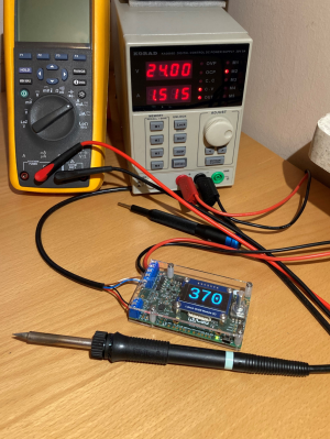
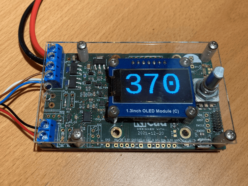
Over on Hackaday.io, user [Tomasz Jastrzebski] has designed a tidy-looking custom controller for driving temperature-controlled soldering irons. The design is intended to be general purpose, capable of operating with irons rated for different voltages and probe type, be they thermocouple- or thermistor-based. Rather than integrating a power supply, this is handled by an external unit, giving the possibility of feeding this from a variety of sources that are not necessarily tied to the grid.
Hardware-wise, we’ve got the ubiquitous STM32 microcontroller in charge of the show, with a nice front end based on the INA823 instrumentation amplifier, referenced to a REF2030 precision voltage source. The input stage is configured as a versatile Wheatstone bridge input circuit, giving plenty of scope for tweaking.
There are a few extra features in the design that aren’t necessarily needed for a soldering iron driver, such as RTC support, complete with supercapacitor backup, but then this doesn’t have to drive a soldering iron, it could drive any DC heater with temperature feedback. With a change in firmware, this could serve other tasks. One potential feature that springs to mind — have the unit automatically power down at a certain time of day in case it was left on accidentally.
The schematic has a lot of relevant detail — in that many parts have a good list of alternatives, presumably because of the semiconductor shortages — which is a good habit to get into if you ask us. Many of us involved with manufacturing have been doing this for years, as it makes sense to give the assembly house the extra options, but this really is basically mandatory practice now.
Firmware for the STM32G0 series microcontroller is based on the STM32 HAL, keeping it simple, with a Visual Studio Code project provided for your convenience. All hardware (KiCAD) and firmware can be found on the project GitHub.
We’ve seen a few projects like this over the years, like this Really Universal Soldering Controller, a custom controller for JBC irons, and this great portable Arduino-based unit.


Automatic power-down? My solution is an outdoor Christmas lights timer, which costs ~$11 at Home Depot. Just add a small piece of opaque tape over the photocell, and set it to 2-hour mode. I’ve forgotten to turn off my soldering a couple of times since I did this a few years ago, so it’s already been worth the effort.
More temperature-controlled soldering irons do need to have this feature, though.
It’d be as simple as activating another timer (assuming this STM32 variant has an extra not being used), and then either setting its match and clock prescalar high enough such that the desired auto-off time is achieved (usually requires a 16-bit timer, which again this STM32 likely has lying around) or using its interrupt to increment a counter (if one is working with an 8-bit timer) until the time is reached. Reset the timer/counter whenever a refreshing input is received. Whenever the threshold is reached, turn off the PWM output. <20 lines of code.
A lot of more integrated modern soldering irons (love my Pinecil) have an IMU onboard that also refreshes the timer, and they will go to a resting temperature after a short span of time (~30s?), ramping up extremely quickly to working temp when it's picked up again. Super convenient, and makes it easier to dig around into that box from Mouser for that last pesky diode without your iron sitting hot. Unfortunately not an option for an external driver. Perhaps, though, the board could infer usage through required current for a longer-term (I'd prefer 5min, or 2hr for you) power-off.
Also love my Pinecil.
There is pure count down timers here, usually 30min, 60min or 360min (6h) versions. They usually use the power line frequency to drive the mechanical timer. I have also seen purely electrical ones but never used them.
Mechanical timers do not use power line frequency. They are mechanical, not electronic. The mechanical timers make use of coiled torsion springs to store energy and rotate gears and (in essence) flip a switch. There are more expensive mechanical timers used for building lighting systems that use the electric motor to wind up a large torsion spring which can sure energy for several hours. The principle is similar. Electronic timers have two varieties, a thyristor switch (triac) or relay of sorts (actual relay or a small motor which rotates to activate a lever switch). The thyristor version is electrically connected to line. If that is understand, connect it’s output to an AC line voltage relay and use the dry contacts. The relay of sorts version may or may not have dry contacts. So, check first. Line frequency is used on electrically controlled or motor controlled timers to maintain time. In north America, the electrical utility adjusts the frequency each night (or used to) to either slow down or speed up to match the correct time. Motors are synchronous types.
I made my own iron controller too, and programmed it to go to a low-power state where it simply defaults to 200°C, if it doesn’t register variations in temperature for about 10 minutes. It’s enough if you’re actively working on something, and if you’re not you just have to hit the encoder button and it’ll go back up to operating temp in no time. Plus there’s no tip corrosion as the solder is solid at that temperature
I have a cheap stm32 based soldering iron from banggood, it is 60W, temperature controlled, has replaceable tips and automatically cools down after a few minutes. It heats up in less than a minute and is capable up to 400 C. It does require an external 24 V source though but you’ve probably got one lying about anyway. It does everything it needs to very well. I would definitely recommend something similar. No need to keep your iron on for two hours when you don’t need too, it’s just wasteful and not the safest and a cheap iron can work as well as an expensive iron.
Really brilliant idea. Do you have a write up on your project? If so please share. If not could you please share more details. Thanks.
This is a very interesting idea: detecting whether or not iron is being used by analyzing temp fluctuations. I may want to test this idea and release firmware update.
I made a control for the T12 tips and for the automatic shutdown I put a button on the soldering iron holder, when it is pressed it lowers the temperature to half and after 5 minutes it turns it off until it is released from the base, (sorry I used Google translator)
Really impressive to make a soldering iron driver, but in the screen’s display is that the heat degrees or what ?
No, obviously it´s rotations per minutes…
Correct, it is Celsius degrees
Yeah, can’t see why not? He could have added some more info or something though
True, I could but then fonts would have to be smaller.
A large F or C in the same font size would suffice. You’re not manufacturing this for volume sales. We all know what it would mean. Anyway, of you took physics, chemistry and do any engineering work, most likely you’re already writing it the same size as the numbers.
+1 for the very nice (for that super low price!) 3005D Powersupply and our de facto golden standard for all our engineers the Fluke 289.
Glad to see others feel the same when buying equipment :)
seems way to complicated, all you need is a potmeter, adc, 8pin mcu
Many parts from the schematic can be omitted if all you need is just iron driver.
The firmware does NOT use Mbed OS, it is purely based on STM32 HAL.
Darnit! Where did I get that from? Looking at the code, yes it’s pure HAL isn’t it?
Article will be corrected. My apologies.
It uses yet another PURE UNOBTANIUM microcontroller. As of my post date – ZERO stock everywhere and more than a year lead-time!
https://www.findchips.com/search/STM32G0B1CE
And oh yes, see this gem: “GM declares chip crisis over—and says it’s time to let the cheap cars roll. 02-Feb-2022, by Christiaan Hetzner”
https://fortune.com/2022/02/02/gm-declares-chip-crisis-over-car-production/
Yup, GM and the rest of us live in different Universes.
Note that there are 10 (ten) alternative MPUs you can use:
STM32G031F8Px/G8Ux
STM32G041F8Px/G8Ux
STM32G051F8Px/G8Ux
STM32G061F8Px/G8Ux
STM32G071G8Ux/GBUx
This design uses STM32G081GBUx specifically because STM32G0 family is pin-compatible, also between QFN and LQFP packages.
@Tomasz said: “Note that there are 10 (ten) alternative MPUs you can use” followed by list of series variant parts – all of which are also not available.- except for one. The expanded the search:
Hi Tomasz, I think I know who you are from the likes of CNX etc., and I appreciate your opinion.
https://www.findchips.com/search/STM32G041F8*
There is this result:
https://www.mouser.com/ProductDetail/STMicroelectronics/STM32G041F8P6?qs=xZ%2FP%252Ba9zWqayYoZl7%2Ff%252BOA%3D%3D
TSSOP-20 only, not QFN or LQFP. Everything else is zero-avail. Maybe my search was a bit too broad. But why is there only ONE chip on Mouser that is in-stock and all other variants are unobtanium? Hmmm…
The point I was trying to make is that this chip shortage is FAR from over, even though big users claim it is DONE:
https://fortune.com/2022/02/02/gm-declares-chip-crisis-over-car-production/
For the rest of us; hobbyists all the way through small and mid-size businesses, the chip shortage is not over at all. So Tomasz when do you think we’ll get back to “normal”?
My mistake, this is the correct list of alternatives:
STM32G031C8Tx/Ux
STM32G041C8Tx/Ux
STM32G051C8Tx/Ux
STM32G061C8Tx/Ux
STM32G071C8Tx/Ux
STM32G071CBTx/Ux (128K)
STM32G081CBTx/Ux (128K)
STM32G0B1CBTx/Ux (128K)
STM32G0B1CCTx/Ux (256K)
STM32G0B1CETx/Ux (512k)
STM32G031C8T is currently available on eBay
https://www.ebay.com/itm/154440621009?hash=item23f560dbd1:g:3E8AAOSwzh1gkj6L
I agree, the situation is.. unusual. General public is kept out of the loop because, best to my knowledge, this is full blown trade war.
@Tomasz said: “STM32G031C8T is currently available on eBay”.
Yeah, these days here’s the rule-of-thumb when searching for chips…
If the chip is in stock and ready to buy, it’s a Chinese fake – either that or your search turned up ‘potato chips’, which (thanks to Brandon) are also getting hard to find and/or afford.