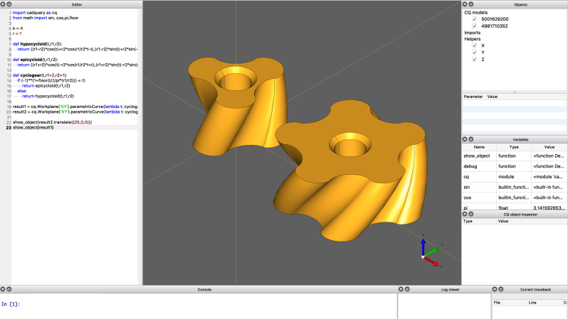
Now, we know what some of you are going to say — “Oh man, not another programmatic CAD tool, what’s wrong with OpenSCAD?” — and you may be right, but maybe hold on a bit and take a look at this one, because we think that it’s now pretty awesome! OpenSCAD is great, we use it all the time round these parts, but it is a bit, you know, weird in places. Then along comes CadQuery, and blows it out of the water ease-of-use and functionality wise. Now, we’ve seen a few mentions of CadQuery over the years, and finally it’s become a full-blown toolset in its own right, complete with a graphical frontend/editor, CQ-editor. No odd dependencies on FreeCAD to be seen! That said, installing FreeCAD is not a bad thing either.
The goal is to have the CadQuery script that produces this object be as close as possible to the English phrase a human would use.
For those that haven’t seen it before, CadQuery is a python library that allows you to create 3D models, and export them as STL as well as STEP, so making models for your KiCAD project is an option too. Unlike OpenSCAD, however, CadQuery is much more design–intent focussed. The idea is to have the python script read more like a human description of the form of an object, as opposed to a bunch of algorithms constructing an object from straight boolean operations, all relative to the global coordinate system. CadQuery uses a relative association model, where things are defined relative to other things. From the docs:
CadQuery is different– you can locate features relative to others in a relative way– preserving the design intent just like a human would when creating a drawing or building an object.
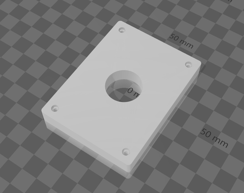
height = 60.0
width = 80.0
thickness = 10.0
diameter = 22.0
padding = 12.0
# make the base
result = cq.Workplane("XY").box(height, width, thickness)\
.faces(">Z").workplane().hole(diameter)\
.faces(">Z").workplane() \
.rect(height - padding,width - padding,forConstruction=True)\
.vertices()\
.cboreHole(2.4, 4.4, 2.1)\
.edges("|Z").fillet(2.0)
# Render the solid
show_object(result)
# Export
cq.exporters.export(result,'result.stl')
cq.exporters.export(result,'result.step')
We’re not saying OpenSCAD is bad, far from it, it’s just different, and for some people, CadQuery is going to be a lot easier to get what you need done. Need a fully-parameterised enclosure to 3D print? How about one done in just 47 lines of python code? As the complexity of the object grows, so does the benefit of the CadQuery approach. There’s a fair few concepts to learn with the tool, as it is pretty powerful, giving many ways to solve problems, but we think the effort will be well worth it. If you don’t like QC-editor, that’s no problem, as CadQuery can be used standalone with whatever editor you like, it even works with Jupyter notebook! Installing it also shouldn’t be an issue, with canned builds available, but that said, it’s a whopper of an install, so we hope you’ve got a spare gig of disk space!
If you are a more visual thinker, and all this coding leaves you cold, then you might want to check out this guide to parametric modelling in FreeCAD, a similar guide for fusion360, or if you’re damned well sticking with OpenSCAD thank-you-very-much, then why not brush up on those OpenSCAD skills.
Thanks [JohnU] for the tip!


A gigabyte installer? I think I’ll damned well be sticking with OpenSCAD, thank-you-very-much.
At least, maybe. At one point I was considering writing a C program to generate an OpenSCAD model, because I was so frustrated with the inside-out “functional programming” paradigm. But I’ve sort of gotten used to it. No telling what I would have to un-learn to use yet another 3D modeling language.
There is no odd dependency on FreeCAD. It’s bundled!
CQ2 does not depend on FreeCAD. It does depend on OCCT (which happens to be the open source CAD kernel used by FreeCAD but otherwise not). The installer *does* bundle all the deps (Python, Qt, PyQt, OCCT, OCP, …), but FreeCAD is not one of them.
There is some historical dependency on FreeCAD for previous versions, but now the same kernel is bundled, along with all the anaconda bloat. Implementation may be a bit sucky, but for what it can *do* I’m happy it exists for one.
Care to elaborate on the sucky part?
🤣
Only problem is that you’ll end up in a mental institution if you try to use it for anything more complicated than making a simple box. The user interface isn’t as much as an interface as a Rube Goldberg Machine designed to make any operation as complicated and painful as possible.
^ This. And complaining about a gigabyte installer? He must be using a PC from 1997. I will never understand the insistance on absolute small at all cost programs. Its 2022 there are terabyte sized hard drives in laptops. This excuse is lame. I get it if you’re doing only number crunching and needing full resources for simulation or something, but come on! If it were a solitare game, yeah, but it’s a CAD system. It’s always from types that use OpenSCAD. Who insist on doing everything, no matter how painful or obtuse, in code, despite the rest of the world finding graphical input for intent far more intuitive.
That’s like saying that if you are a billionaire, it doesn’t matter if a cheeseburger costs $10,000. Maybe it doesn’t, but on the other hand, if everything uses 1000 times as much as it needs to, then that terabyte drive might as well be a gigabyte. I don’t buy big drives so I can waste them on bloatware; I buy them because I have DATA that needs them.
“I will never understand the insistance on absolute small at all cost programs.”
lol. not *at all cost*, but size…man…a program that is 10x larger than it needs to be, 100x, 1000x, 10000x, 100000x…i understand no one is going to reinvent GL or CSG just to save a few bytes. there will be some bloat in favor of code re-use, and that’s a reasonable cost to pay. but how much cost?
tbh, i’m pretty sure a big strike against openscad is that they decided to use opencsg instead of reimplementing it themselves. openscad is dog slow for operations that do not need to be so slow…every time i run it, i pay the cost of their decision to reuse an overly-general CSG library when their actual object model has a lot of constraints that could be taken advantage of to do *much* faster operations. and another strike against openscad is a totally gratuitous dependency on Qt, when i don’t even use their GUI at all, nevermind that their GUI is so simple it doesn’t even use 1% of the code they pull in in Qt. Qt is not just so many megabytes of download, 3x that many megabytes of storage, and so on…it’s also a huge dependency nightmare that breaks other parts of the system…and then people add new virtualization/containerization features to manage that dependency nightmare, resulting in another 3x storage consumption…it gets really absurd. and at the end of the day, you go to do an update or to install something new and your computer is still wedged, and the number of things you have to debug to get it unwedged has grown and so many of them are new so you have to do a more expensive process to debug it. that’s a cost.
at *WHAT* cost is the question. not at all costs. when i hear that something has a 1GB installer for a really simple program that is just a thin wrapper around existing libraries, that isn’t unacceptable by itself but it is a huge hint that when they decided which existing libraries to build upon, they made poor choices. i’ve never heard of opencascade and i don’t know anything about the freescad dependency but from people talking about it here, maybe simply looking at it and saying “if they have 1GB of dependencies, they made poor choices that reveal an overall poor design” was a useful shortcut and learning the details of the baked in flaws in opencascade and etc would just be so much wasted time. time i saved by using this heuristic about bloat.
I did something non-trivial in it. Not very non-trivial, but it drove me completely mad. It has a really weird idea of what object orientation is and lots and lots of hidden state. Bleurgh!
What are you even referring to here? Did you try to download the installers for every platform or something? Because CADQuery’s releases on Github are a few megabytes, and the GUI editor is 212MB-371MB, depending on your platform.
@Dave Rowntree said: “…CadQuery can be used standalone with whatever editor you like…”
Well probably not, in Windows anyway: “CadQuery Prerequisites: Anaconda/Miniconda…” [1] AFAIK in Windows Anaconda and Miniconda are installer-only downloads, there are no stand-alone or portable versions.[2][3] In my past experience Anaconda/Python has an uncomfortably big footprint in Windows when stomping around in the Environment and Registry settings. Also, it did not uninstall cleanly. But that was a couple of years ago, maybe it’s better now. One thing is certain, Anaconda is big: “Python 3.9 64-Bit Graphical Installer (510 MB)”, and that’s the compressed download!
* References:
1. CadQuery QuickStart
https://cadquery.readthedocs.io/en/latest/quickstart.html
2. Anaconda Installers
https://www.anaconda.com/products/individual#Downloads
3. Miniconda
https://docs.conda.io/en/latest/miniconda.html
I hear what you’re saying and yes it is a bit of a mess still, but my point (clearly not made, er, clear) was regarding just the editor bit – I don’t really see why you can’t write the code part in atom or even notepad++ if your really wanted to. The Jupyter support is nice though – gonna give that a go tonight. I’m learning CadQuery now, and properly going to give it a go with a real project.
I understand. In-fact an editor is listed as a prerequisite, but I did not mention it because I agree with you, any editor/IDE/front-end will work.
Better use: https://github.com/conda-forge/miniforge
On win this is quite portable (i.e. just installs to a folder):
start /wait “” build/Miniforge3-Windows-x86_64.exe /InstallationType=JustMe /RegisterPython=0 /S /D=%UserProfile%\Miniforge3
Interesting, thanks. But to me that looks like more than a simple “just installs to a folder”. Also the Windows install instructions start with an installer: “Download the installer and double click it on the file browser.”
Great to have ready made installers! I’ll have to give this another try, last time I tried in 2020, I got stuck in the installation when “miniconda” just wouldn’t co-operate.
Anaconda/miniconda is far and away the worst thing about cadquery. It looks pretty fantastic once you get over that hurdle, though. STEP is great for import from/export to “”more traditional” CNC fab processes, and having a real programming language available is great when you’re doing more generative projects. And fewer of the “weird broken STL file” issues that crop up with import/export from openscad. Cadquery isn’t *entirely* absent of them: it will come to a dead halt if you (eg) try to make a 2mm fillet on a solid with a face that’s 1mm wide in one spot, and those issues can be quite annoying to diagnose at times. But this sort of thing is much less common than with openscad, and in general you’ll find yourself filleting and chamfering with wild abandon because it’s so much easier than with openscad.
I’ve got a /very/ extensive repo of openscad projects and libraries… but I’m never going back. Cadquery is just so much better.
If a software package doesn’t fix their software installation process — how great can it be, really?
I’ve just wasted most of an hour trying to get it to install on a Mac before giving up in a mess of confusing Conda errors.
I found it much easier to skip anaconda altogether and instead create a Python virtual environment and install with pip. Maybe worth a try.
For those who want some good FreeCAD and even, Blender tutorials for 3d printing, MakerTales on Youtube has some excellent ones that I’ve been using for a while.
Okay, so Blender isn’t truly a CAD design program, but I’ve found some times it’s all I’ve really needed for simple designs, and sometimes even more complicated ones can be created with it.
If you haven’t done so before, I would recommend checking his videos out at: https://www.youtube.com/c/MakerTales.
DISCLAIMER: I am in no way associated with MakerTales, but I have personally found his tutorials very useful and informative.
The main problem (other then Anaconda) is that it is still based on OpenCASCADE – the only opensource CAD kernel in existence – which AFAIU is opensource because it was thrown out as a garbage already in 80s.
I just ran across https://github.com/CadQuery/cadquery/issues/896 and I’m crying my eyes out from desperation. Such basic functionality broken in 2022 and the problem is coming from OpenCASCADE.
Other than that, CadQuery is wonderful compared to OpenSCAD because OpenSCAD is only a primitive *generator* where you can’t *query* already build geometries and you CANNOT WORK AROUND it manually, because you can’t even return values from modules (like manually calculated bounding box, or some attachment points in global coordinates, etc..)
Solvespace manages without OpenCASCADE
Not necessarily better though. As soon as you have a few intersecting curves, SolveSpace just fails in NURBS booleans randomly.
– no support for expressions and variables dependencies
– no way to instantiate and use part multiple times with different parameters
– no extrude along path
– no loft
– no sweep
I love the concept but the implementation leaves much to be desired.
i don’t get it. as near as i can tell it’s not really different from openscad in terms of its expressiveness? does it really offer anything useful extra other than fillet and chamfer? like, openscad can make stuff relative to other stuff, that so-called limitation of openscad is bogus. and making false claims about limitations that openscad doesn’t have shows up in the comments here, too: “you can’t *query* already build geometries and you CANNOT WORK AROUND it manually”. you may not like how openscad forces you to structure this kind of interaction (function vs module vs constant) but re-use of objects and intermediate values defining those objects is very possible in openscad, it’s just a lot more awkward than you probably think it should be (see #3).
i have 3 complaints about openscad.
1. some geometry is almost impossible to specify…i’d like to have something like multmatrix() but with arbitrary expressions instead of just linear factors, like multmatrix([[a,b,c,d],[e,f,g,h],[i,j,k,l],[0,0,0,1]]) could be expressed as transform(x=a*x0+b*y0+c*z0+d, y=e*x0+f*y0+g*z0+h, z=i*x0+j*y0+k*z0+l), and then the transform() could accept more complicated expressions. the problem with actually implementing this is that openscad would need to insert a lot of extra vertices in the primitives in order for it to be useful…basically violates their object model.
2. it’s slower than i think is reasonable, but i don’t know why.
3. assignable local variables would be handy on occasion.
i only care a little bit about #2 and #3, they’re both easy enough to work around. but #1 is a hard limit that stops me dead on certain projects. there are totally different models for interacting with 3d shapes, which i think would solve #1 and #2 at once. i did, surprisingly, find one project that re-implemented the openscad language using a superior 3d shape model that would be capable of solving #1 but they didn’t actually follow through with it, they just used it as a hack to solve #2. it feels like the sort of thing i’d have to do myself, and i’m unlikely to get around to it.
anyways, i don’t think this python thing really deals with any of the real problems with openscad that i have. it might be a lot friendlier for someone, but it doesn’t do anything for me. i guess i don’t know what i’m missing with fillet and chamfer.
It is extremely different. OpenSCAD is just a generator. As I stated above you can’t reference an already drawn geometry even if the geometry is drawn by OpenSCAD itself and is not imported externally.
You can’t even get such basic things as bounding box. And even though you know bounding boxes of all your primitives you cannot use them to calculate bounding box of composite shapes…
Consider following example: union() { cube([30, 20, 10]); translate([100, 0, 0]) cube([10, 20, 30]); }
How do you automatically calculate bounding box? You can’t. You can’t even compute it manually because you can not return anything out from modules other than some drawing which you also can’t reference, just blindly modify from parent modules.
And bounding box just one example.. even if OpenSCAD had some special support for it it would still be gloriously insufficient. Even though I have serious problem with anything conda related, CQ itself is nicely written and astronomically more capable than OpenSCAD just because it can do queries. Heck it has *Query* in its name!
And I’m not even touching the subject of OpenSCAD language itself which is sorely missing support for structures and functional programming.
Yeah, I’ve run into this several times. It has forced me to take the long way around to determine what the location of a particular feature will be with the parameters, rather than what would have been a simpler matter of just MEASURING where a particular feature ended up. OpenSCAD is the classic case of someone who doesn’t really understand programming languages, writing one because they need it in a project. It works fine for that project, but you’re forever finding things it just won’t do because it wasn’t designed to do them.
I’ve been using OpenSCAD for years, and have produced hundreds of individual designs with it, and never once have I run into any of these issues. If I created the objects from my own variables, why would I need to query something to see its dimensions? What would I need a bounding box for?
I’m honestly curious, as it seems like your expectations of the software must far exceed my own.
Because locating a feature from pure math is effing damn hard.
To give you an example: say you subtract a cylinder from sphere and you want to place stuff at regular intervals along the intersection line.
Sure in theory, you can compute the equation of the intersection and compute the curvilinear abcissa along the border.
You’d better have Mathematica handy though, cause doing it by hand is going to take a while.
Grawp is refering to how you might have an object with a pin-hole in it, structured like:
module obj() { translate(ofs1) translate(ofs2) cylinder(…); }
and if you want to use those coordinates again, you have to either repeat “translate(ofs1) translate(ofs2)” or re-structure your code a little:
pin_coord = ofs1+ofs2;
module obj() { translate(pin_coord) cylinder(…); }
and to add insult to injury, since openscad doesn’t have assignable local variables (nevermind returnable ones), if pin_coord is a function of the arguments to obj() then you wind up with some more convoluted hack like:
function pin_coord(v) = […];
module obj(v) { translate(pin_coord(v)) cylinder(…); }
Grawp is imagining some syntax probably roughly like…
module obj(v) { translate(v) translate(ofs2) { pin_coord=here; cylinder(…); } }
var x = obj(v); translate(x.pin_coord) …
where you can save a location in the middle of a nested / relative expression and refer to it later. iow, to “query” an object to ask about its parameters.
And of course, if your objects DO have the ability to return values, then you need an object class declaration and all that entails, and before you know it you’re back to a procedural programming language. Which I would rather have had in the first place. Enter CadQuery. But based on people’s reported experiences, I don’t think I’ll be knocking my head against this particular wall.
yawn. i already said, “you may not like how openscad forces you to structure this kind of interaction (function vs module vs constant) but re-use of objects and intermediate values defining those objects is very possible in openscad, it’s just a lot more awkward than you probably think it should be”
i agree, it’s a little awkward to do this kind of thing in openscad. and i think it’s an unforced error…like BBJ says, a sign that the language designer didn’t really do their homework. but it’s well and truly possible, you just have to hold its hand..you have to do some steps you don’t consider elegant or convenient. again, like BBJ said, “the long way around”.
i’ve groaned a couple times because of this sort of thing, and it does make my list of problems with openscad. but it’s at the bottom of that list, and it has never been something i couldn’t easily work around. if cadquery can’t help me with the top of the list then i’m not really interested in it.
There is a very fundamental difference between the two.
OpenSCAD is CSG modelling system. I.e. you put together primitives like cylinders and boxes using boolean operations. I.e. to make a plate with 4 holes you make a box and subtract 4 cylinders from it. And that is also *why* it is so tricky to do operations such as chamfering, filleting or lofts, because it is not something that can be easily expressed using a composition of boolean operations on primitive bodies. Instead one has to mess with convex hull operations, Minkowski sums and what not – which are all extremely computationally expensive and don’t allow an easy mental representation of what the result is going to be after the long computation.
CadQuery is based on OpenCascade which is a BREP based system. BREP stands for “boundary representation” – in a very simplified way this means the bodies (solids) are expressed using their boundary – faces, edges, vertices and, crucially – their geometric relationships (e.g. “this body is made out of these faces, face #1 is composed of these edges which contain those vertices …”).
This is different from something like an STL file containing a triangle mesh. That one has the faces and vertices but completely lacks the “structural” information about the geometric relationships between pieces. That’s why it is so hard to make meaningful modifications to it.
BREP is the representation that allows you to do things such as chamfering edges or extruding faces in a very simple way – very common CAD operations that people are used to from other CAD systems (which are almost entirely BREP based as well). That’s also why it is possible to support STEP (which is BREP based) and that OpenSCAD will probably never support.
CSG modelling is historically older, BREP was developed later and quickly replaced it in almost all CAD applications because it is much more expressive and easier to use (don’t confuse it with the programming language used to interface to the kernel, OpenSCAD can be also used from Python, for example).
There is no conceptual conflict between BREP and CSG. You can have a CSG tree evaluate to a set of BREP primitives, or, in the case of OpenSCAD, evaluate to a set of tesselated solids (i.e. closed hulls composed of triangles). The frustration, for me, with OpenSCAD is that it throws away a lot of the potential of CSG by evaluating to triangles too early; that is, primitives are built from triangles long before its necessary. I presume this simplifies a lot of its design, but I feel as though the meshing parameters are something which should be applied as late as possible to the evaluation process e.g. during rendering or export, and should be user specified or even adaptive to achieve the user’s goals.
It’s described as being similar to human speech, but that code example proves otherwise. The amount of punctuation here is a little excessive I’d say. The only thing that looks more readable is the variables, but that’s just a matter of naming your variables better in openSCAD.
I dunno. It looks really busy to me. A lot more keywords to learn. What I’d really like to see is their cheatsheet. I’ll go look for that now.
While my previous comment sits in limbo, here’s the api reference list. It’s pretty big. I do think this could be useful, and I’ll probably give it a go, but for smaller less complex models: I don’t think I’ll be uninstalling openSCAD.
https://cadquery.readthedocs.io/en/latest/apireference.html#apireference
If you like the idea of CadQuery but are more comfortable working with JavaScript syntax and want to use the BRep OpenCascade kernel (not a CSG kernel like OpenJSCAD), CascadeStudio is worth knowing about. It was kind of hard to get started in when the only documentation was a small demo and auto-completion with Intellisense, but now raydeleu wrote an introductory manual that really helps get started and also has some really thoughtful comparisons to other systems; including listing things available in CadQuery but not in CascadeStudio.
https://github.com/raydeleu/CascadeStudioManual/blob/main/readme.adoc
https://zalo.github.io/CascadeStudio/
I’ve liked being able to share a model with anyone with a browser merely by sharing a URL that contains all the code for generating the model locally. ☺
2 disclaimers to open: First – I am not a CAD person, I am a database person., Second -I am a database person who preferred for decades to write all the code my DB programs used – from entry to sorting to reporting. Did not use anyone’s tools. Why? If the code “broke” I could fix it since I understood how it all worked together. (and back then my stuff would leave dbase IV and its cousins in the dust.)
That is part of the problem now – we have gone from simple – everyone understands – graphics formats to using GPU’s to do the heavy lifting because the ‘things’ being manipulated are so complex. In college I wrote a program for an arbitrary assignment that was physically the smallest program that could do the task, and it was so slow compared to the larger programs that used a few dozen more lines of code.
The comment in the article was that the INSTALL took a gig – Not that the installer needed a gig. For a program that can manipulate and render complex objects in 3 space – and generate output for essentially 3 space printers – that is not such a large amount of storage space.
The Linux operating system is as complex as WIndows in many areas – and Neither requires less than a few hundred million to a billion or more lines of code spread out over tens of thousands of files (including driver code for all of our toys to work and be able to talk to us.)
Usefulness does not require that a program be small. It requires that the program be efficient on your computer, and for the time you use it. If you can’t get work done, it does not matter what the CPU is or the OS that is running the show.
Again, I am not a CAD person, but if I was I would be investigating in-use videos to see if it was more efficient than my current process – and THAT would drive my use or avoidance of the program, not how big it was on my hard drive.
heh, sometimes the faster implementation is a bit larger, it’s true. and i do love to use a general program when it’s convenient, even if it’s slower or larger. but since you mention databases…i have a database i implemented in mysql (myisam), storing temperature data every 30 seconds from 4 sensors around my house. 10 years of data grew to 2GB and to render all of it took *for ever*. i started benchmarking and realized that simply getting the data out of mysql was the bottleneck. a distant second was gnuplot. the overhead of putting perl in the middle of these two didn’t even make the list. well over a minute to display a single year’s data.
the thing that finally motivated me is that whenever mysql shut down uncleanly, on start-up it would need to copy the whole database to a temporary file and then copy it back. an extra 2GB of scratch requirement, and it took hours to do it, and it never worked…i would always have to manually intervene once i realized it was AWOL. i couldn’t shake the feeling that one day it would wipe the whole thing and i’d have no recourse.
rewrote the database in 750 lines of C, rewrote the display (replacing gnuplot) in 921 lines of C. it now does 14 years in 112MB and can render all of it to PNG in 9 seconds. it’s not any slight against mysql or gnuplot, they were both just awful for the tiny subset of their functionality that i needed. i appreciated their functionality while i was designing it, but after i’d used it for a while their downsides dominated.
it’s not that 1GB is too high a price to pay for a good program…it’s that 1GB demonstrates an attitude towards dependencies that is almost never coincident with good programs.
I’m a programmer who wants to learn CAD so I can make things with my 3D printer. This looks like the perfect tool for me to get started.
I’m kind of excited about this. As much as I like OpenScad, the language is pretty awkward, and CadQuery’s choice of Python with a fluent API seems promising.
But it seems really weird to me that the cboreHole() call in the example seems to be returning the box object rather than, anything else in the chain of operations between the call to box() and the call to cboreHole(). I gather there’s a stack of objects implied by the chain, but it seems weird to have that stack be implied rather than explicit.
Part of the reason cadquery uses conda is to get around all the C++ libs that need to be used / built
I recently tried this under windows and it wasn’t as bad as it used to be
install miniconda (this is conda without the thousands of science packages pre-installed)
Untick both boxes when it asks about the path etc
Then:
# Update conda
conda update -n base -c defaults conda
# change directory to some place to install
cd C:\Apps\
# create a virtual conda environment
conda create -p cadquery
# Activate
conda activate C:\Apps\cadquery
# Install
conda install -c conda-forge -c cadquery cadquery=master
There’s also this for integration with vscode
https://github.com/bernhard-42/jupyter-cadquery
Yes – and can’t manage even what that “garbage, thrown out in the 80s already” OpenCascade kernel can do.
Writing a geometric kernel for CAD is a highly non-trivial issue requiring fairly specialized knowledge from mathematic, geometry and, obviously, programming. Not many people around who have it in the first place and even fewer who are going to start an enormous project like this for free.
” what’s wrong with OpenSCAD?”
– The lack of object orientation.
– All a function can do is return, no local variables or statements inside. Ok, sure it’s good that it eliminates side effects but sometimes writing everything you need in one long block of conditional operators.
– The lack of true variables.
– No ability to query the dimensions of an object. (Especially bad when dealing with text, oh the kludge that is necessary to make something grow to fit text)
– No ability to query an object for it’s orientation.
I’m not sure if all this is because the designers were trying to make it “not a programming language” for non-programmers ease of use or if it’s just that brain-dead anti-reuse functional programming fad.
But even a beginner, if their goal is to design parts to 3d print is going to want these things quick. And I can’t imagine any other use is OpenSCAD’s primary use.
Imagine being able to do something like this.
//Pick your fastener
fastener=”M3HexCap”; //[“M3HexCap”, “M3Countersunk”, “Num6Countersunk”]
//Minimum side length
min_side = 10;
//Height
height = 5;
import
bolt = new Bolt(fastener);
module cube_with_bolthole(bolt, min_size, wall_thickness, height){
side = max(min_size, (2 * wall_thickness) + bolt.head_diameter));
difference(){
cube([side, side, height]);
translate(v) bolt.draw_printable_hole();
}
cube_with_bolthole(bolt, min_side, 2, height);
Imagine also if draw_printable_hole() had the smarts to know when it is horizontal and arched it’s top part up a bit to compensate for droop when bridging. Perfect holes without drilling!
draw_printable_hole() would draw just a smooth shaft and basic head shape. It would extend the head up a bit so for flush mounting it would still break the surface since it’s going to be used inside of difference().
Other methods could be something like draw_photorealistic, with teeth, no head extention and including the indent for the driver.
Other classes in the library could represent nuts, washers, heatset inserts, etc…
Sure, much of this is technically possible using what’s there but it involves lots of modules and functions all thrown into the global scope, sizes stored in vectors where one must count positions, etc… and there is no way to measure a drawn shape or it’s orientation.
I think you may be going too far, there. There are good reasons we separate CAD from CAM: CAD describes the object, and CAM is the fitting of that object into the fabrication process.
Here are some off-the-top-of-my-head reasons:
1) You can select the CAD application that fits what you’re trying to make and how you think, without having to worry about whether it supports filament printing or whittling from a bar of soap, or whatever.
2) You can take a model that you originally made using FDM for example, and with minimal or no changes, fabricate it with a resin printer.
3) You can update your CAM software, and instantly add functionality to your workflow, regardless of the CAD system. Or vice-versa.
I’m guessing you are talking about the idea of knowing the orientation of an object and altering hole shapes based on it?
I thought that might be kind of a controversial feature although I didn’t quite entirely describe my idea and the rest might put you at ease.
Sure, normally one uses the CAM tool (or slicer in 3d printing terminology) to chose the orientation of the object. There isn’t really a good way to do what I am talking about in a slicer though. Have the slicer recognize horizontal holes and stretch the top of the hole upward a bit to counter the distortion inherent in the printing process? Show me a slicer that can do that? The slicer would have to have a concept of what a horizontal bolt hole is which at that stage is going to require a pretty good AI. It’s much easier back at the CAD application where one is defining a bolt hole and could have say.. a bolt hole class that knows how to do this.
Remember, in my original post I did state the assumption that the majority of OpenSCAD users are doing so for 3d printing. But even if one uses OpenSCAD for something else, I’m not suggesting that OpenSCAD itself do this to all horizontal holes. I’m just talking about a language feature allowing one’s code to know if it’s orientation so that the user could chose to write that.
Besides that, I would imagine that the exact degree of distortion would vary between printers, filament types, etc… I was imagining having a global somewhere to define the amount of distortion. Then there would be an optional part one could print with holes of various distortion amounts, pick the best one and set the constant.
Someone using a different process or who wants to re-orient the part in the CAM tool would just pick 0 distortion and nothing would change for them. That could even be the default if one doesn’t know how their design is going to be used.
Really, I was talking about things like having the CAD program modify the shape of a hole to compensate for how the printer is going to distort it. But what you point out is another flaw: the slicer SHOULD be able to change part orientation. The fact that slicers don’t do this just means that the developers of the slicers don’t understand the role of their software, which is to process a 3D model to prepare it for the fabrication hardware. Which is Computer-Aided Manufacturing. The fact that slicers don’t do this does not mean it isn’t the job of the CAM software; it just means that developers are incredibly narrowly focused. I use OpenSCAD to make models for filament printing, but I also use it for things that are going to a CNC router, or even to be fabricated using a table saw and a drill press. It is decidedly NOT a good assumption that OpenSCAD is only for 3D printing. It is a CAD (Computer-Automated DRAFTING) program, not a 3D printing program. And as I pointed out in my response, there are good reasons NOT to include fabrication features in CAD programs. If you have a fabrication feature you need, and it’s in your CAD program instead of your CAM (or “slicer” if you prefer), then you’re stuck with only those CAD programs that happen to have that feature.
To me, software is a tool. I don’t pick software for being able to do everything from beginning to end of a project, any more than I expect my oven to be able to slice my pizza. I have other tools for that.
I don’t think you are getting the problem. Based on your use of the word CAM I am guessing you come from more of a CNC than an FDM printing background. There are similarities but differences too.
To do this after all your solid objects (such as cylinders) after converting to STL would be kind of like un-cooking your pizza to fix the spices in the crust.
The point is to compensate for the droop that occurs when the top wall of a tunnel (horizontal bolt hole) is printed with molten plastic. Not really a concern with solid materials. At the point the slicer sees it that tunnel is not a discrete object like an OpenSCAD cylinder(). It’s a needle pattern among a giant haystack of triangles.
But the problem isn’t just with horizontal cylinders. If there is a drooping problem for overhanging surfaces, it’s a problem whether they were modeled as cylinders or as rectangular tunnels, or an extruded circle, and this can be determined by the angle of each triangle in your stl mesh. You don’t have to uncook the pizza for this, because to the printer, it doesn’t matter how the tunnel was modeled. I can’t make my point much further with the pizza metaphor, because sometimes you DO need to cook certain toppings before sending the whole pizza to the oven, so I’ll just leave that alone. I do more FDM printing than any other tCNC, but once you’re doing ANYTHING besides FDM, you’ll see the value in applying methods at the appropriate place in the workflow. And I don’t have a shop full of CNC machines, anyway, so it’s not like I don’t understand hobbyist-level fabrication; I have an under-$200 CNC engraver and a filament printer. But as I’ve already said, I also do 3D modeling to visualize projects, even if I’m not using CNC at all, and I don’t want to see my lasagna cut into eight wedge-shaped slices just because that would be cool for pizza. There, I got the pizza metaphor to go one step more ridiculous. And sure, if you want these things to be done by the tool that shouldn’t have to think about wheter a hole is vertical or horizontal, if you’re loud enough you can probably get someone to add that feature to whatever CAD tool you like to use, so knock yourself out. I mean, my oven has features I never use, so it doesn’t cost me anything, anyway.
I thought about this more last night.
I thought it would be too difficult or at least much more for the slicer to recognize where it needs to apply the deformation after the object has been rendered to STL because my cylinder is no longer defined as a single cylinder object but rather is only a pattern in the pile of triangles.
I’m still not convinced that doesn’t make it harder at the slicer (or CAM) level but I suppose it probably is possible since the slicer does already have the intelligence to find things like overhangs and generate supports.
Maybe it could be done. But it’s going to take someone patching the slicer that has a large set of skills and knowledge that I wouldn’t even know where to begin to obtain. And it’s probably going to slow the slicing process to a crawl.
On the other hand, I really only use my Slicer’s ability to generate supports when I am printing someone else’s designs. I just haven’t had a whole lot of positive experience with slicer generated supports. They tend to connect to the part in all sorts of spots I don’t want them to, leaving marred surfaces and generate way more supports than are required. It’s gotten better, most slicers give the user more control than they used to but the state of this is still pretty crap.
In my own designs I try as best as I can to pick one surface that is naturally going to be the bottom (thus I’m not too concerned about using the slicer to change orientation). With a bottom surface chosen I then design for the least possible number of overhangs. Where I MUST have an overhang I try to include a 45° slope so that no support is necessary. Where I actually must have support I define a wall, as thin as my printer can print that only supports the end and let it bridge. In the end the wall peels away so easy and leaves little to no marking, much better than slicer generated supports.
But when I share a design I don’t force others to do it my way. If you use a different fabrication process that doesn’t need supports, if you prefer the supports your slicer generates that’s all fine. I always include an easy parameter to turn my supports off. I also make that wall thickness a parameter so you can tune it for your own printer.
So anyway, what I want isn’t for the CAD package to automatically decide where deformations or supports are needed. I don’t want OpenSCAD or a replacement to know anything about 3d printing. I want to be able to design an object, myself, in my code which deforms itself. But to do so it has to know which end is up. And yes, I know which end is up as I write the code. I can do this all manually. But how much neater would it be to just call Bolt.Draw() and have it know for itself which end is up and so deform itself appropriately.
All I want from the CAD package is proper objects and for those objects to know at draw time the sum of all the rotation transformations they might be nested inside. There are probably other reasons, someone else would use the same feature that have nothing to do with the printing process.
And again, I always parameterize this. If you downloaded my OpenSCAD code and wanted to fabricate the object on a many-axis CNC it’s no problem. Set supports_thickness and hole_deformation both to 0 and you are good to go. And I put my parameters in the customizer with lots of description so really, not a problem.
i agree with your list of criticisms of openscad, though (as in my post earlier), i wouldn’t rank them among my biggest complaints with openscad. in particular, your example illustrates clearly why I don’t: i can (and do) re-use fastener patterns with existing openscad syntax. your example reminds me of people saying you can’t do OOP in C…you can! sometimes it’s uncomfortably verbose or encourages mistakes, but in this example it is so simple that there is no advantage to having the language provide OOP support intrinsically.
but there are cases where it really would be helpful. it’s just that the most common cases happen to work out fine even with openscad’s primitive language design, which is why people are satisfied with it even if we know and sometimes meet those limitations.
but mostly i’m replying because your example is so perfectly an example of harmful commenting habits:
//Pick your fastener
fastener=”M3HexCap”; //[“M3HexCap”, “M3Countersunk”, “Num6Countersunk”]
//Minimum side length
min_side = 10;
//Height
height = 5;
the code is improved by removing those english-language comments! it actually is less readable because of your style here! and it’s such a common mistake among people who think they need language support for OOP — even in this tiny example you’ve got enough garbage on the screen with no effect that it’s hard to find the small amount of code that does anything, to understand what you’re trying to suggest. when there’s hardly anything there, that’s when you get the most advantage from not obscuring it.
god i can’t stand looking at code trying to guess what it does because it’s got so much non-does-stuff content.
Strongly disagree on this one. Putting comments on lines of code that the user has to edit is an absolute necessity. Without that, they may change variables that SHOULDN’T be changed, because they’re not going to analyze the design deeply enough to know what is what. Also, if you think that writing comments makes it HARDER to figure out how something works, then all I can say is, you’ve seen some pretty poor comments.
“all I can say is, you’ve seen some pretty poor comments.”
//Height
height = 5;
the thing is, you say the comments indicate user-editable values. i find that frame pretty foreign — everything is user editable, that’s why i’m using code in the first place. but failing that, the fact that these 3 values were intended to be edited by the user was *not* provided by these comments.
Maybe you don’t understand what “user editable” means. One of the principal reasons for using OpenSCAD is to build models with parametric adjustability. The “user” in this case is a person, including myself, who wants to be able to take advantage of these parametric features without f*ing up the basic model for any other use.
So you don’t think that “//Pick your fastener” is an invitation to edit?
You are complaining about the comments?
What comments?
You just betrayed your ignorance of OpenSCAD.
Those “comments”, in that format are there for the customizer tool, not the next programmer. If you show the customizer window in OpenSCAD’s UI or if you use various web based customizer tools it parses those comments and presents the user with a dropdown labeled “Pick your fastener” with the options listed in the vector after the // and two textboxes labeled “Minimum side length” and “Height”.
Also, yes, I do know that the re-usability can be achieved despite lacking OOP. I’ve seen some wonderful examples out there where people have really gone out of their way to make it work. It’s just really ugly in the ways I described, requiring a bunch of module names polluting the global scope and parameters stored in giant vectors where one must count places to find a specific field.
What do you do when you want to include two libraries that use the same module names?
I guess you can prefix every module name with “SomeDumbAndLongIdentifierThatPROBABLYNoOneElseWillIUse_”. Yuck!
What a dumb limitation!
The best way to do OpenSCAD.. 3 sections.
First section, define the variables that a user might want to change. Use that comment format Greg hates because that’s how one does labels and multiple choice options in the customizer. These all have to be before any other code because that’s where the customizer looks.
Second section, the code that actually generates your part wrapped inside a module. The purpose of wrapping in a module is so that another programmer can bring in your code using the “use” command and pass parameters to it w/o just automatically generating the part with default parameters.
Third section, actually call the module, passing the parameters that were defined at the top.
If you want to include multiple parts in the file then one of your parameters at the top is a combobox naming the various parts. In the second section define each part in it’s own module. In the third check the value from the combobox to see which method to call.
You can also include an extra option that calls all the modules and positions them as they will be assembled to use as a guide. Or even sub-assemblies if your project warrants that.
Don’t forget to add even more options to the combobox for drill guides. To generate a drill guide for a part just call it’s module inside of the projection() operator. Then the user can select that one, export to PDF, and print.
Come on Greg, catch up!
I don’t think CadQuery is ever going to take off until it is available as a downloadable application that I can just download and be ready-to-go, just like OpenSCAD. Having to deal with conda and the nightmare that is a python dev environment is not enjoyable. I would rather just be working on my modeling projects in OpenSCAD than spending half my time fighting conda and python.
Saying that though if the installation problem could be fixed I see some promise with CadQuery. Being able to work on individual faces and position things in a local coordinate system that then gets translated to the global coordinate system behind the scenes is really nice.
However, every time I sit down to start learning more CadQuery, conda and python get in the way and I have to try to fix yet another environment issue (currently trying to fix a problem where Sketch() isn’t available in the cadquery module even though the documentation clearly shows it is).
Also, with OpenSCAD, for non-programmers wanting to customize my parametric designs, I can give simple instructions for installing OpenSCAD and opening the built-in customizer. With CadQuery there is no way I could provide instructions for someone to customize my design. Heck, I make my living as a programmer and even I have problems (mentioned above) getting a reliable cadquery dev env.
So as much as OpenSCAD sometimes drives me nuts, it is the current best programmatic CAD option available. (My biggest pet peeve with OpenSCAD is that you can’t return values from modules)
So, I found CadQuery a couple of days ago but before playing around with anything, I first look for reviews, comments, etc, like this thread…it sounded good enough to give it a try.
Since the last comment above is from 2002-Feb, I figured I would update.
Installation of cadquery 2 is available directly from pypi with the ‘–pre’ qualifier; it installs in less than a minute…no anaconda, no nothing. ;-)
At this time,
size of pip installing cadquery? 542MB
size of installing cq-editor? 1GB
Greetings.
Oops, typo…2002-Feb meant to be 2022-Feb, obviusly
Ha, ha…and obviusly meant to be obviously, obviously
Sooo…I see no sign of a list of processor vendor requirements but a ‘find in page’ on my browser says that ARM processors aren’t supported. Game over for me then. :-D