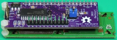
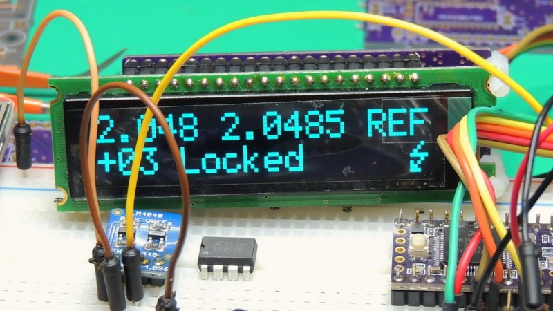
Back when LCD character displays based on the HD44780 controller were the bee’s knees, a way to make them easier to work with came in the form of “backpack” PCBs, which provided an accessible serial interface and superior display handling at the same time. [Barbouri] has updated that idea with a backpack board that mounts to OLED displays using the US2066 display driver, and provides an I2C interface with powerful and convenient high-level functions that make the display simple to use.
 On the software side, the backpack uses this I2cCharDisplay driver project which provides functions like cursor control, fading, display shifting, and of course writing characters or strings. While [Barbouri] designed the board specifically to accommodate Newhaven Slim Character OLED displays, it should in theory work with any US2066-based OLED character display. [Barbouri]’s design files for the Slim-OLED Display backpack board are available for download directly from the project page (link is near the bottom), or boards can be purchased directly from OSH Park.
OLED technology is nifty as heck; we’ve seen some neat tricks done by stacking transparent OLED displays, and even seen OLEDs made in the home lab.


Whenever I try to design one of these boards for the common LCD1602 / 2004, I always end up at the same place.
I want to control the contrast – so PWM into a capacitor to get -ve to +ve range and another cap to filter out the AC of the PWM and a temp sensor to compensate but hey most uC’s already have that. I want at least on/off control of the backlight or a brightness control or even in some cases RGB or a bicolor LED so I have a color (Flashing RED) to indicate an alarm condition that can easily be seen from a distance. Once again any brightness / color control has to be filtered so that the PWM doesn’t interact with the display refresh rate unless you just go with 3 colors from a bicolor LED.
Ok, So need a couple of passive analogue bits and bobs. So I just add an 8 bit serial to parallel shift register and run the display in 4 bit mode and I’ve saved enough pins not to have to worry about any additional board on the back of the LCD.
The standard add-on boards won’t do the extra features and they’re always a serial to parallel expander of some sort. I think a board with a cheap PIC would probably do all I want and actually bring it down to one simple I2C or SPI device with phantom registers for the extra features.
So yeah, could have done it with a 74LS575 or any 8 bit SIPO register.
Interesting that you mention pwm interacting with the lcd refresh rate. This was an issue I faced years ago with an early prototype I was making for adding an rgb backlight to monochrome gameboys. My first prototype bitbanged the pwm at rather low frequency (iirc maybe a few hundred Hz) and caused a weird strobing effect on the lcd. I ended up optimizing the software to generate 2kHz pwm and the strobing went away and the final version used another chip with hw pwm at higher frequency without issue.
The visual issue occurs when the two frequencies (refresh and PWM) or a lower harmonic of one or both the two frequencies are within about 20Hz of each other. It still occurs at other frequencies but we just don’t see it.
Most cheap LCD’s vary in frequency quite a lot so just relying on higher frequency PWM alone can be hit or miss even though the odds are in your favour at higher PWM frequencies. Even the ATmega’s have a higher PWM frequency in one pin, it’s about 1.5kHz from memory.
It’s probably likely when you get up to much higher PWM frequencies that parasitic capacitance is reducing or eliminating the amplitude of the effect.
For contrast I just CR filter it to below about 10Hz and it’s all good because there is (practically) no load so I can use a high value resistor. I capacitively couple to the PWM so that I have a voltage ranger that goes negative as well.
For R,G and B leds (three of) then a CR low pass before a buffer transistor is better. You should be using a buffer transistor anyway off the pin of a uC.
There, isn’t anything that I know of that you can do with an addressable LED as the PWM frequency is fixed internally.
I’m not sure the writeup has the right idea – there is no ‘software side’ to this.
The backpack isn’t doing any local processing – it’s just a few I2C devices (OLED, GPIO expander, EEPROM) and voltage regulation co-located on a PCB.
I would agree, this is a driver library for Arduino, to make accessing the US2066 functions easy to use when writing code. It is entirely optional and not needed for the OLED display interface board hardware to function.
The github page mentions an available software library to handle strings, as well as what’s effectively wrapper functions to send commands via I2C which are then converted by the aforementioned serial US2066 chip on the backpack which interfaces with the oled via the HD44780 parallel protocol. So a host mcu would run the library to say take user fed strings, transmit over I2C, which the US2066 would convert to parallel to feed the oled.