The late 90s and early 2000s were a breakout time for mobile phones, with cheap GSM handsets ushering in the era in which pretty much everybody had a phone. Back then, a popular way to customize one’s phone was to install a sticker that would flash when the phone rang. These required no batteries or any other connection to the phone, and [Big Clive] has dived in to explain how they worked.
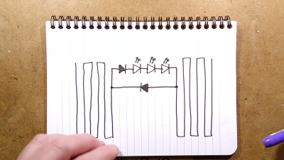
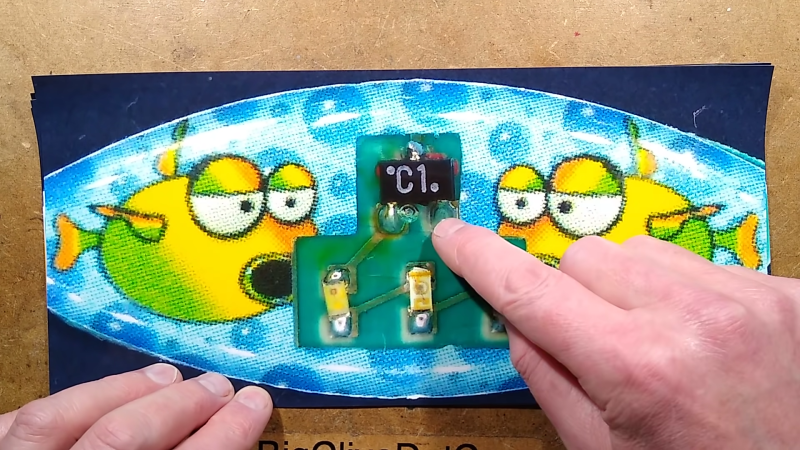
It’s an old-fashioned teardown that requires a bit of cutting to get inside the sticker itself. A typical example had three LEDs in series for a total voltage drop of around 7V, hooked up to two diodes and a PCB trace antenna. A later evolution used raw unpackaged components bonded to the PCB. Future versions went down to a single diode, using the LEDs to serve as the second. The basic theory was that the PCB traces would pick up RF transmitted by the phone when a call was coming in, lighting the LEDs.
In the 2G era, the freuqencies used were on the order of 300 MHz to 1.9GHz. A combination of the change in frequencies used by modern phone technology and the lower transmit powers used by handsets means that the stickers don’t work properly with modern phones according to [Big Clive].
Incidentally, you might like to consider running your own old-school cellphone network. Video after the break.
https://www.youtube.com/watch?v=https://www.youtube.com/watch?v=fVmLyladBy8
[Thank to Zane Atkins for the tip!]


freuqencies?
Freudian slip?
Depends on the waevelnght
What is the frequency, Kenneth?
I think the closest you’ll find to the old 800 / 900 MHz bands now is ISM bands. 2G still works on 900MHz in some places but the phones RF output will be much lower than in those days.
I mean besides the 800mhz band LTE and 5G-NR, and the 650mhz and 700mhz LTE and 5G-NR. But the transmit power is still a lot smaller and burstier
Resonance,
I remember making a powered version of this form a miniature am radio back in the nineties, it could run several less and had the added bonus of an audible alert. It would trigger a few seconds before the phone would respond. Essentially giving me time to put down my soldering iron before I had a answer a call or text message.
I never knew of those blinkers then.
I remember those days when my phone caused a POS user at a quick mart to command me to step back because my phone was causing his terminal to hit the enter button with every RF pulse emitted whilst he had to void them all.
Oh yes, I remember when my stereo told me, incoming!
That time when computer speakers, and radios notify you of incoming sms/calls before your phone does!
GSM TDMA 400KHz pulse rate causing the speakers to make noise…
Oh yes. Beep beep beep boop door doot dooooooooootttttt
Used to know someone then who could hear or feel those signals. They’d always say “you’re receiving a text” and your phone would beep. Creepy AF
It’s 2022 and you still believe the “harmful cell phone radiation” myth? Grow up. You know bananas set off Geiger counters. You going to stay away from bananas now?
The article mentions the LEDs light up when you are receiving a call (implying the RF energy transmitted from the cell tower would light up the LEDs) but intuition tells me the received energy must be way too small for that. However when the handset starts transmitting back to the cell tower in response, and the LED sticker being mere millimeters away from the antenna, then there should be enough energy to capture using the antenna and light up the LEDs.
Nah , it’s when your receive a call. Your phone response to the first transmission at Max power and then turns forth the power once you have the connection going. Ah this is before your phone rings
Never had that here in USA. At least, never saw a soul here using those. Also, turned 30 in 2000, so that might be the reason I never saw one as well. Was working at a well known Wall Street firm to boot back then, so conservative phone etiquette was the thing.
@Martin, the USA was mostly using CMDA (or TDMA?) at the time, they were (relatively) slow to adopt GSM. Not sure if it was malice by the telcos or an old FCC regulation that made it harder to implement GSM compared to e.g Europe and the UK.
I’m glad Big Clive is building notoriety and a fan base. He does a great job at reverse engineering. There isn’t much he hasn’t torn apart.
Came here to say much the same thing. Between his charming brogue, and his detailed and varied reverse engineering videos, I have lost many an hour to his channel. Glad to see him featured here!
A couple antennas between a diode strapped to the side of a transmitter?
Sounds like all sorts of non-linear mixing would be going on inside. I wonder if phones with these stickers were causing a lot more out-of-band interference.
Early this century, when a works Christmas party was being organised, I was told who I was buying a secret Santa presents for. One got a Beano Annual. The other got a battery operated mobile phone rest which played a tune as the phone gave its maximum output response to an incoming call. After the party the recipient drove home, passing Heathrow Airport on the way. Turned out it was going off repeatedly, no doubt triggered by the electronic fog around the site.
I remember, years ago, youg people use this stikers on they’re nokia 3310 ( and other cell phones to, but more on 3310/3330 ). And i was fascinated by them ! It was the fashion of the moment !
” young people “, i mean, sorry for the mistake
Remember the flashing antennas for the Nokia 5110?
I want one so bad for my 5110, cannot find one anywhere
A loop would have an easier time coupling energy from the transmitter.
In the near-field, the antenna inside the typical mobile is probably driven by currents to launch the transmission using magnetic fields.