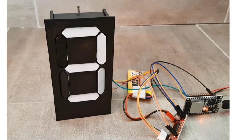
Sometimes the cost of simplicity is extra complexity. It seems counterintuitive, but it seems to be true. And this single-motor mechanical seven-segment display seems to be a perfect example of this paradox.
 On second thought, [aeropic]’s mechanism isn’t really all that mechanically complicated, but there sure was a lot of planning and ingenuity that went into it. The front has a 3D-printed bezel with the familiar segment cutouts, each of which is fitted with a pivoting segment, black on one side and white on the other.
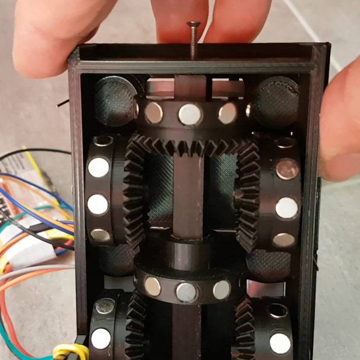
Behind the bezel is a vertical shaft with three wheels, one behind each horizontal segment, and a pair of horizontal shafts, each with two wheels behind each vertical segment. The three shafts are geared to turn together by a single stepper in the base. Each wheel has ten magnets embedded in the outer circumference, with the polarity oriented to flip the segment in front of it to the right orientation for the current digit. It’s probably something that’s most easily understood by watching the video below.
We’ve seen quite a few of these mechanical seven-segment displays lately — this cam-and-servo mechanism comes to mind. We love them all, of course, but the great thing about [aeropic]’s display is how quiet it is — the stepper is mostly silent, and the segments make only a gentle clunk when they flip. It’s very satisfying.


Ooh. Clever!
Whoa! That’s pretty great, need to add that on to my bucket list.
Really nice!
It would be nice to see it in fast action, like homing in and then quickly moving to current time
Since there is some inertia in the segments, it cannot move too fast between two numbers Anyway, for a clock, a change every minute, it is fast enough.
In the demo video you see the homing sequence which lasts around 10 sec (one number per second)
https://youtu.be/fM9fBpv1Tc0
I think I can say, I doubt I’d ever have thougt to use physical magnets to store the bits for a seven segment decoder. Very out of the box. Certainly a lightbulb moment when I saw how it worked. Great post.
thanks!
Definitely clever. Is this an original idea?
Thanks.
Yes, it’s an original idea. i made deep researchs on the web and could find anything approaching… The idea came from those electromagnetic flip dots displays. My intention was to avoid hte complex H bridge drivers!
* could not !
Bon, maintenant ta mission c´est un afficheur 16 segments sur le meme principe, ok ?
LOL
A simple option, and one I will likely pursue, is to have each solenoid double wound and only driving one of the windings at a time, which means twice the copper but half the transistors.
Hi all,
Thank you all for those positive comments and above all to Dan for your so cool post. I think you perfectly got the idea behind this little display: a KISS idea (Keep It Smart and Simple … or Stupid :-) )
I would like to see some makes… turn on your printers !
Meanwhile, I slowly start building the 4 digits clock but there is some work …
This is a very neat, clean and clever design. I love it!
Loved the design that you have produced amazing keep it up.
I cant shake the feeling I’ve seen a similar project on HaD before….
Similar as in only on motor per 7-segement part.
Maybe with 7 specific sets of sprockets for the segments instead of magnets?
Anyway, still nice idea!
And if you want to build a large counter you can daisy chain several of these together and use only one motor in total (with 10-to-1 reduction gears between the modules).
But only for increasing numbers…
Oh yes, there are several one stepper motor designs (including the one mentioned in Dan’s post) but none with a perfect shape of segments ;-)
It was likely that one: https://hackaday.com/2021/06/27/mechanical-7-segment-display-uses-a-single-motor/#comments
Also rather simple and nice concept, but this one got extra credtis for the properly reversing segment and the smooth move (love the way each segment oscillates shortly before stabilizing!)
yeap, this one is cool as very flat, but it is quite huge to give room enough for the wheels.
At the end of a digit change I perform by firmware a small oscillation of the wheels, this is to help unsticking the segments in case one is blocked. This oscillation helps to introduce the stabilization effect, even if the inertia of the segment would be enough I think!
Great. Reminds me of the other mech display called Bina-View!
So cool ! That’s a big seven seg mechanical display !
I think it would have been good to show movement between non-sequential numbers, showing that the segments would settle to whatever arrangement of magnets was ended on, though the motor zipped through intervening positions. For example, a dice-rolling example using 6 (or even 10) digits.
The magnets are too close on the rotating disks and there is always a residual magnetic field that forces the segment in one single position… No possibility of random position here !
This is the best one motor, mechanical 7-segment design I’ve ever seen. The magnetic encoder is elegant, and now affordable thanks to commodity rare-earth magnets. (I’d love to see a video of its “random access” display speed). It is true that most clock digits mostly count +1, +1, +1, and the 0-5 “tens” clock digits can omit a lot of magnets to skip back to zero without visiting 6-9. I didn’t analyze the electronics interface beyond understanding the “reset at 2” sensor. I always encourage emphasis on making the software simple too. I am likely to use an alternative to the ESP32. School children will want to use Scratch and/or LEGO robotics. Maybe some software-shy, mechanical wizard will make an entirely mechanical digital clock. Seems doable now. I’d buy one!