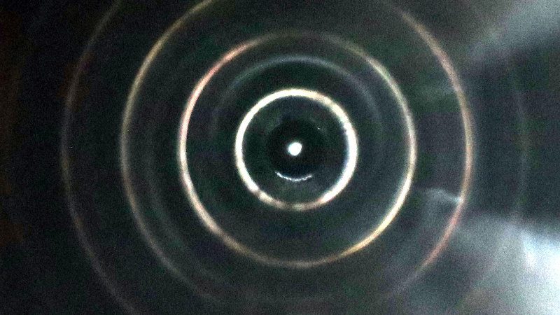
There should be a line of jokes that start “A physicist and an engineer walk into a bar…”. In my case I’m an engineer and my housemate is a physicist, so random conversations sometimes take interesting turns. Take the other day for example, as one does when talking she picked up a piece of aluminium extrusion that was sitting on our coffee table and turned it over in her hands. It has a hole down its centre and it’s natural to peer down it, at which point her attention was caught by the appearance of a series of concentric rings of light. Our conversation turned to the mechanism which might be causing this, and along the way took us into cameras, waveguides, and optical fibres.
The light reaching us after traveling along a straight narrow tube should at a cursory glance be traveling in a straight line, and indeed when I point the extrusion out of my window and look down it I can see a small segment of the tree in the distance I’ve pointed it at. It didn’t take us long to conclude that the concentric rings were successive reflections of the light coming into the end hole from off-centre angles.
In effect, the extrusion is a pinhole camera in which the image is projected onto the inside of a cylinder stretching away from the pinhole rather than onto a flat piece of film, and we were seeing the successive reflections of the resulting distorted image as they bounced to and fro down the tube towards us. It’s likely the imperfect mirror formed by the aluminium wall allowed us to see each image, as light was being diffused in our direction. Adding a piece of tape with a small pinhole at the end accentuated this effect, with the circles becoming much more sharply defined as the projected image became less blurry.
The Annals of the Bleeding Obvious
So great, we’ve invented the pinhole camera, where’s our Nobel Prize? Our place in the esteemed scientific journal Annals of the Bleeding Obvious is evidently assured. But on the other hand, we’ve explored the mechanism used by light pipes and fibre optic communication, namely the passage of light along a waveguide through successive reflections from its internal walls.
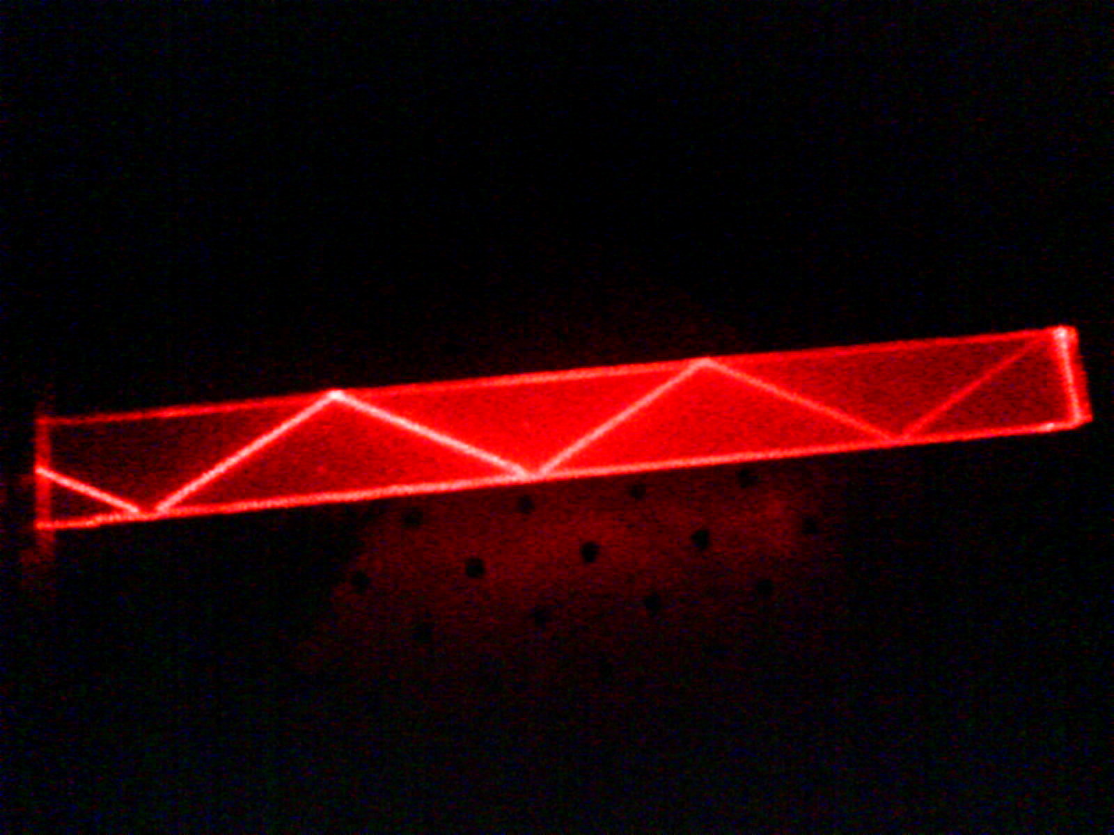
It’s not much use with a piece of extrusion because it’s bulky and not flexible, but when the medium is switched to a piece of laser-cut acrylic the same technique can be used to great effect. Edge-lit acrylic displays are hardly a new idea, but in the age of the LED and perhaps more pertinently the expensive Nixie tube, they appear to have made something of a comeback.
Of more interest is the idea that each of those concentric rings is a successive reflection of the image projected by the pinhole. In our idle discussion around the coffee table we surmised that with some image processing or suitable lenses it could be mapped from a cylindrical reflection to a flat one in the manner of a photograph we’re all used to. Could such an image travel round curves in the light pipe and be used for remote sensing? That scientific journal just called again, we’ve just invented the endoscope.
What have you reinvented lately?


Of course, there are tons of jokes about a mathematician, a physicist, and an engineer.
That would be ‘metric tons.’
Looking through the small side of a 3D printer nozzle I noticed even from fairly far back I can see perfectly through it and not only that but the size of what I’m seeing looks more like what I would see looking through the larger hole on the other side. I was at first very surprised to make out any image through the 0.4mm hole but the weirdest part is the light/image of what’s coming through that 0.4mm hole looks to be what I’d expect looking through the other side of the nozzle which has a hole size of 2mm that extends about 12mm into the nozzle leaving 0.5mm of material for the 0.4mm hole to taper down to. The light/image that does come through looks to be almost filtered as if looking through a very fine mesh screen making the image appear dimmer.
I had thoughts of reflections, waves turning to particles and vice versa or a lens trick where you can reduce light through a polarized lens then shift the polarity back and get the light back even though it was already filtered out by the first lens. I’m working with a 8th grade education so I’m likely missing something.
In general, any aperture smaller than the pupil of your eye will appear to make a dimmer than “natural” image, because it does not leverage the full light gathering area of the pupil of your eye. Your pupil though, changes size according to illumination. So in a bright lit room it might be 3mm, so you might not notice much dimming through a 2mm hole.
This kind of thing is most noticeable in the selection of binoculars for astronomy and low light work. The objective in mm divided by magnification, gives the “exit pupil” size. Now in dim light, your pupil opens way up to as much as 7mm. So while you might assume a pair of binoculars with 25mm lenses and 10x magnification is superior to use in bright daylight for spotting birds, because they’re light, easily handled and you see 10x bigger… compared to the clunky old 7×50 dinosaurs you got off your Pops.. but then try them both at night, you’re getting a now tiny, much smaller than pupil size 2.5mm “exit pupil” out of the 10x25s and can’t even see as much as you can unaided, while the 7x50s are almost like night vision, cramming their pi(50/2)^2 light gathering area down to an “all you can eat” 7mm exit pupil for the dark adapted eye.
This is way to good to be just a comment. It should be a section of an article on telescopes/binoculars
Sorry, but I didn’t get it – You looked through the hole and saw the world on the other side. What is unusual?
Saw it again, and again, and again…. and wondered why.
Around the 2005 I was having dinner with a friend at my parents house and taking with my father first about punch cards, then about punch tapes. My father told us how the contacts off the reader can wear out and I told we can use a light source at one side of the tape and some kind of photodetector on the other side. This way there are no contacts to wear. Then we talked about putting the tape on to an spiral and using some encoder to know the angular position of the tape/disk. Then you put a reflective coating over one side of the disk and move the sensor next to the light emitter… And I said “shut up, we have just invented the CD-ROM!”
Sorry for any misspellings and or grammatical errors, I’m not a native english speaker, so please, be kind.
So this makes me wonder if one can make an efficient telescope out of a shiny tube and a fresnel lens. With the fresnel used as an eyepiece, and only the internally shiny tube used as the objective.
However, there would be a relationship between the diameter of the tube required and the spacing of the concentric fresnel prisms on the fresnel lens…. so one would probably have to empirically determine size of tube needed by rolling up shiny material and testing it with fresnel lenses one managed to source (Like wallet size “credit card” magnifier reading aids etc)
One problem though is keeping the fresnel lens sufficiently centered to “sync” with the concentric rings while experimenting.
And… does the reflective tube have to be one long cylinder, or could it be chopped into coaxial, incrementally widened sections with mirrors/”prisms” at ends connecting them all into one long light path?
What’s weird is that random light coming in from all angles doesn’t create an equally random series of reflections that covers the entire inside of the tube.
I wonder if you could compute an inverse of the projection, so that you could display a warped image on a TV screen and view it through the tube and see a normal image. I guess it might only work for images that had a kind of radial repetition. Would still be an interesting art project.
I wonder if this could be used to measure the consistency of the extrusion. It’s quite tricky to measure because of how reflective it is.
Yes!
I just recently peered through a curtain rod. The patterns shifted when bending the rail slightly and were not concentric any more.
Generally straightness isn’t a huge issue as far as I’m aware. When it comes out of a press it goes into what is called a stretcher which pulls it all very straight. Because pushing hit plastic metal from the rear can create bends. Even though when the extrusion comes out of a press it is pulled forward at the rate it is being extruded by a series of pullers. Kind of like pulling taffy but you want to pull at the exact speed it’s being extruded.
Though maybe straightness is an issue. I’ll ask some people.
There are other deformities that can occur as the press adjusts it’s speed. Usually those get cut out or it makes the extrusion scrap. But I’m wondering about dimensional consistency.
And I just thought being an extrusion you were looking at the wall imperfections made during manufacturing.
You do but shiny aluminium is hard to measure. And is also generally too hot to use touch sensors on, even cameras that look at it need to be air cooled. A lot of it is just checked by hand since there is time after extrusion.
Structural aluminium extrusion might be different.
Relevant optical phenomenon: https://en.wikipedia.org/wiki/Caustic_(optics)
It’s caustics all the way down…
I wondered where the name “caustics” came from. Immediately I thought of caustic chemicals, but how could that be related to light phenomena. Wikipedia to the rescue.
When I got my first green laser pointer I shone it down a length of Aluminium tubing to see the effect. It would produce a ring which could be adjusted in size by changing the entry angle of the laser. Misting the air at the exit of the tube would show that the exiting beam was in a cone shape. I never tried bending the tube but I would imagine if you had a white or full spectrum laser the bending my produce chromatic aberrations in the beam circle
Consider recalibrating your imagination. Chromatic aberration is caused by dispersion; the change in refractive index of a medium with respect to wavelength. Light does not enter the metal. Refractive index is not relevant in the reflection of light from a metal, and chromatic aberration cannot occur.
I came up with the concept of the 58K dialup modem (trimmed to 56k by FCC regs) back when I started working with ISDN.
I thought it was too simple. Simpler than the 9600baud modems out there. Big companies with people smarter than me with lots of money hadn’t done it, so it must not work.
Took over 2 years for someone smarter with more money than me to start making them. In fact it was such a simple idea that they wound up reprogramming the brand new, still on the shelf, 48K modems to do it.
I was trying to figure out clever ways to connect internal combustion engines to turbochargers and would go on the same tangent every once in a while; why not replace the internal combustion engine with a combustion chamber, oh, never mind, that’s been done before.