When it comes to high-speed, high-voltage switching, there are a wealth of components to choose from — MOSFETS, thyristors, IGBTs, and even vacuum tubes like thyratrons. But who needs all that expensive silicon (or glass) when all you need to build a high-voltage switch is some plumbing fixtures and a lathe?
At least that’s the approach that budget-minded laser experimenter [Les Wright] took with his latest triggered spark gap build. We’ve been watching his work for a while now, especially his transversely excited atmospheric (TEA) lasers. These are conceptually simple lasers that seem easy to build, at least compared to other lasers. But they do require a rapid pulse of high voltage across their long parallel electrodes to lase, and controlling the pulse is where this triggered spark gap shines.
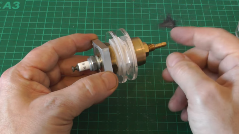
The spark gap is made from brass plumbing fittings on either end of a short PVC coupler. [Les] used his lathe to put a thread into one of the caps to accept a spark plug, the center electrode of which pokes through a small hole in the metal cathode. To trigger the spark gap, [Les] built a trigger generator that outputs about 15,000 volts, which arcs from the spark plug electrode to the spark gap cathode in the low-pressure nitrogen environment. Little spark leads to big spark, big spark discharges a capacitor across the laser electrodes, and you’ve got a controlled single-shot laser. Check it out in the video below.
Honestly, the more we see of [Les]’ videos, the more we want to play with lasers and high voltage. From DIY doorknob caps to blasting Bayer arrays off cheap CCD cameras, there’s always something fun — and slightly dangerous — going on in [Les]’s lab.


Back in the early 80s, I built a 1 megawatt Blumlein TEA laser for an undergrad Physics project. Basically a windowed acrylic box to contain the N2 and a couple of square feet of double sided PCB as a transmission line. The EMP when it fired usually showed up in the equipment in the labs near mine. 15KV at 40 KA switched through a sparkgap in a few nanoseconds. No shielding? My bad…
What are Kelvin*Volt and Kelvin*Ampère? If you allow me to be that guy.
They’re like normal volts and amps, but with old-timey frock coats and big mutton chop sideburns and beards.
To be fair, all the prefixes bellow 1 is written in lowercase letters.
And all prefixes above 1 are written in uppercase letters except “k” for 1000.
So to a degree, writing an uppercase K for a thousand isn’t in my opinion wrong, and follows the overall logic better as well.
Confusing it for Kelvin is technically a risk. But we already have TT for Tera Teslas.
Also smaller than 1 is Greek and larger than 1 is Latin. Back in 1800, what educated person didn’t read Greek and Latin?
“Also smaller than 1 is Greek and larger than 1 is Latin.”
KILOgram. MEGAhertz. TERAbyte. CENTImeter. WRONG.
Well, the names are from the following language:
Yotta (10^24) Greek/Latin (Depending on who one asks)
Zetta (10^21) Latin/French (Depending on who one asks)
Exa (10^18) Greek
Peta (10^15) Greek
Tera (10^12) Greek
Giga (10^9) Greek
Mega (10^6) Greek
Kilo (10^3) Greek
Hekto (10^2) Greek
Deka (10^1) Greek
1
Deci (10^-1) Latin
Centi (10^-2) Latin
Milli (10^-3) Greek
Mikro (10^-6) Greek
Nano (10^-9) Greek
Piko (10^-12) Italian/Spanish (Depending on who one asks)
Femto (10^-15) Danish (Fermi were for a time the prefix in common usage.)
Atto (10^-18) Danish
Zepto (10^-21) French
Yokto (10^-24) Greek
It is mostly Greek, and Latin is generally more prominent on the smaller side in daily use. (all though, some people not using the matric system don’t believe in Centi and Deci, though I have rarely seen someone use Deka in practice.)
Somehow Danish manages to have 2 terms, this is due to Niels Bohr a rather well known physicist from Denmark. (That somehow managed to out influence Enrico Fermi.)
Decameters is actually a common unit in meteorology. It puts most of the heights of pressure levels at convenient 3 digit values, while the decimal places aren’t that important.
At least it’s not as bad as space rockets exploding or falling out of the sky because of the length of an ancient kings foot or the distance apart horses were on ancient Roman carriages.
You mean because some geniuses flush with revolutionary fervor said “lets start with a totally new standard of length a little longer than a yard”. If they had practical smarts it would have been “lets divide a standard yard into 100 units so weights and measures don’t get all confused” and all would be lightness and joy. We call it a meter and it = a yard.
Awesome, I built the same back in the day, but it has been refined somewhat in my latest designs. Yeah, EMP is a real issue. I need to source a suitable enclosure for it.
Cheers!
So it’s a home-built trigatron?
Pretty much, but its a nice easy build! :-)
I have some problems with this and it may be great and do it’s job but some details or nit picking if you want to call it that.
1) The international space station isn’t a cow. We give them different names because they’re different. The same applies to thyristor, SCR and TRIAC
1) In the schematic a 2N3904 supposedly inverts an incoming pulse however it’s is in a common collector configuration which is non-inverting.
2) The schematic at about 10:49 (although it doesn’t show the PSU or 500V step up) shows a lot of chassis (ground) symbols. As far as I can see the metal plate (front cover) is only connected to the BNC socket.
3) There is a high voltage insulator on the +1500V output but no high voltage insulator on the -1500V output. They don’t seem to have any fixed reference to any ground. The trigger input is opto isolated.
Re: Thyristors and SCR’s, are the same device, the terms are interchangeable. Triacs on the other hand are a different animal, and the MOC3020 opto isolator is indeed a Triac as described in the video.
Re: 2N3904, yes, it was an error spotted on the schematic by some watchers. It is in fact a 2n3906.
Re: Grounds, sure if this was a metal chase, everything would be connected to chassis ground. The negative rail of the input supply is grounded on the front panel.
Re: The insulator, the output is 15kV, and is quite necessary, though admittedly a recessed Alden style HV connector would have been better. The negative side of the trigger transformer is not ground referenced, but float at about -250v (not clear on the diagram admittedly, but disclaimer, I did say “simplified diagram”)
Cheers!
Hi ,
Nice trigger design and as can be seen in the video, it works very well.
However I find the swapping of the sparkgap with the capacitors, as compared to their layout on your non-triggered TEAs perplexing.
The capacitors end up in series with those of the channel reducing therefore the capacitance across the spark gap and hence changing the resonance.
While having no problem copying your non triggered gear and getting them to emit, I am so far unsuccessful in obtaining anything more than triggered spark flashes from the channel.
Your emissions on this video also look rather white and broad as compared to the ones from your excellent non-triggered gear.
Any ideas?