It’s a problem we all have at one time or another: your five-meter radio astronomy dish gets out of calibration and you don’t have a ridiculously expensive microwave holography rig on hand to diagnose it. OK, maybe this isn’t your problem, but when [Joe Martin]’s parabolic antenna got out of whack, he set out to diagnose and repair it, and then wrote up how he did it. You can download the PDF from his radio astronomy articles collection.
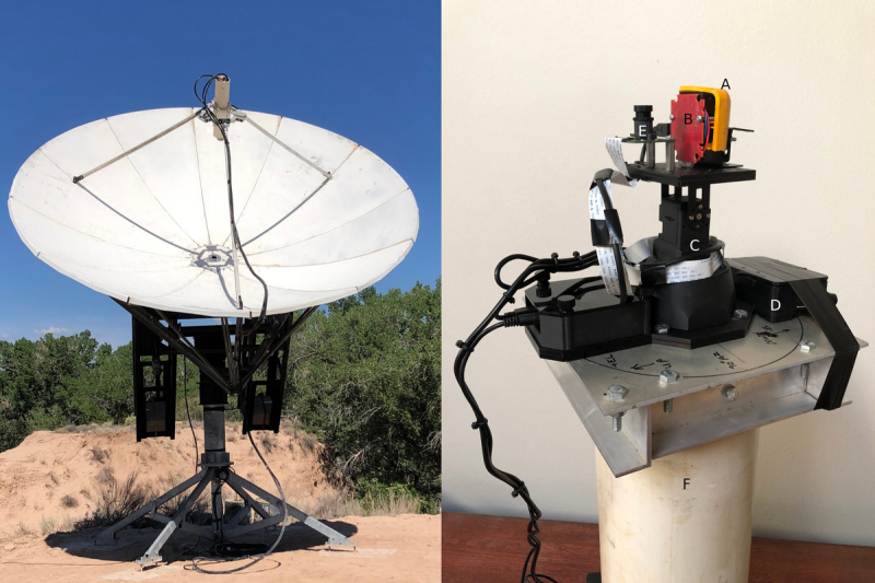
At the heart of the measurement rig is a laser rangefinder connected to a Porcupine Labs interface that passes the data on to a Pi 4. This is placed on the end of a two-degree-of-freedom servo gimbal that scans over the surface of the dish, measuring its shape. After measuring and math, [Joe] found out that it’s a little bit long here and short there, he attached two cables with turnbuckles to the front of the dish and pulled it back into shape — the sort of thing that you should probably only do if you’ve got a measurement rig already set up.
The Fluke rangefinder and Porcupine labs interface combo is pretty sweet, but it comes with a fairly hefty price tag. (Nothing compared to a professional dish measurement rig, we presume.) We’ve seen a few attempt at hacking into el-cheapo laser rangefinders, but other than [iliasam]’s heroic effort where he ended up writing his own firmware, it doesn’t seem like there are any successes. A shame, because applications like [Joe]’s prove that there’s a need for one. Let us know if there’s anything we missed?
Thanks [Ethan] for the tip!


Oh good. I was having problems picking up transmissions from Turkmenistan. ;)
why only one? radioastronomy is easy for increasing mirrors (light is difficult)
I hate it when that happens.
I wonder if you could get approximately the same result by filling it with water while pointing directly upwards and then adjusting the turnbuckles to get the same waterline all the way around.
This gets you extra engineering credit, as you are using “you can’t push a rope”, plus “water runs downhill”
Water is heavy, it will distort the antenna.
Gas vapor?
It’s much cheaper & easier to use the “String Method” the dish manufacturer recommends. A dollar for a roll of string is your only cost. Is much larger than a 5m antenna, then go more detailed with alignment, but depending on the dish, stressing areas with cables can do more damage than good! Something to consider…
[K5SO]’s work is impressive, and properly documented. However IMO using the sun to measure the main lobe half-power beamwidth is a bit dicey. I wonder if the G/T of the 4.63m antenna at 8.4GHz is good enough to run a main lobe sweep on Casseopeia-A? Hmmm… link budget needed.
Using a radio source in the radiative far field would be ideal. But for 4.63m and 8.4GHz the radiative near-far field boundary is rather far away:
(2 * 4.63^2) / (300 / 8,400) = 1,200m [1]
I’ve seen something similar to this (but much simpler) done on commercial antennas. In those cases before the subreflector is mounted a bracket with a tie point at the prime focus is affixed and a measurement wire is used at predetermined points to see where adjustments are needed. Adjustments take several forms (come-alongs, jacks, mallets) and can be quite rough. I seem to remember Vertex Antenna (now CPI [2][3]) used to call the process “Accu-Pound”.
Further adjustments can be made by running repeated antenna pattern sweeps on a satellite beacon and adjusting the subreflector position and tilt. The antenna manufacturer specifies the pattern mask with sidelobes to be met. A rigger with a walkie-talkie and a set of wrenches can end up stuck in a bucket lift for hours or days adjusting the subreflector on a small to medium sized antenna. On large antennas the rigger lives strapped behind the subreflector. The final patterns along with the G/T and EIRP measurement results are sent to the spacecraft operator’s Tracking Telemetry & Control (TT&C) station for approval before the earth station is allowed to operate on its assigned transponder.
* References:
1. Antenna Near Field & Far Field Distance Calculator
https://www.everythingrf.com/rf-calculators/antenna-near-field-distance-calculator
2. CPI Satcom & Antenna Technologies Division
https://www.cpii.com/division.cfm/15
3. CPI VERTEX ANTENNENTECHNIK GmbH
https://www.vertexant.com/
Could’ve used a cardboard shape to lay over the surface. I bet it might even be more accurate.
Not very practical for a 5m dish.