Today, we shall talk about how [Adam Bäckström] took a DS3225 servo and rebuilt it to improve its accuracy, then built a high-precision robot arm with those modified servos to show just how much of an improvement he’s got – up to 36 times better positional accuracy. If this brings a déjà vu feeling, that’s because we’ve covered his servo modifications before, but now, there’s more. In a year’s time since the last video came out, [Adam] has taken it to the next level, showing us how the modification is made, and how we ourselves can do it, in a newly released video embedded below.
After ordering replacement controller PCBs designed by [Adam] (assembled by your PCBA service of choice), you disassemble the servo, carefully setting the gearbox aside for now. Gutting the stock control board is the obvious next step, but from there, you don’t just drop the new PCB in – there’s more to getting a perfect servo than this, you have to add extra sensing, too. First, you have to print a spacer and a cover for the control board, as well as a new base for the motor. You also have to print (or perhaps, laser-cut) two flat encoder disks, one black and one white, the white one being eccentric. It only escalates from here!
Both of these disks go inside the motor. That is, you have to pry the servo’s DC motor apart, take its base with brushes out, then insert the encoder disks. Then, you snip and file away at the base’s plastic parts to free up as much space inside the motor’s base as possible, and add the optical encoders in the space you freed. Once that’s done, you solder the motor, the optocoupler and the potentiometer connections to the new controller PCB, and assemble the motor back together.
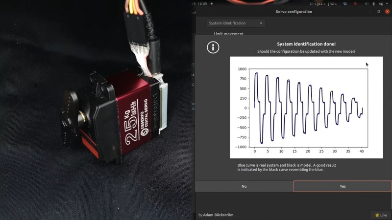
After you’re finished with the surgery, you have to calibrate your servo, for which [Adam] shows how to properly set it up mechanically, provides the code you need to run, and even nice GUI tools with controls to tweak servo parameters – his firmware gives us way more power than we could ever expect from a servo like this. All the knobs and sliders available to control coefficients, limits and curves, show us that [Adam] really does understand what makes for proper servo movement. Enough care is put into the documentation, the explanations and the tools for this modification process, that we don’t have to be anxious about being left behind if we are to follow these steps ourselves!
In a robot arm, small accuracy errors at the base scale into large errors at the arm’s end. If what you crave is high accuracy on a budget, and you have a bit of time to devote to modifying stock servos, this approach might be just what you need, and [Adam] has basically laid all the groundwork for you. Last time we talked about these servo modifications, one of our commenters suggested that this could be a viable successor to the goals of the OpenServo project, and we definitely see where they’re coming from. What if you wanted to go even less expensive than this? You could build a servo out of junk DC motors with a “3 cent” microcontroller, then.
We thank [sarinkhan], [Diede] and [BaldPower] for sharing this with us!


Oh my god. I am amazed. Also 2:15-2:16 that was awesome =)
Go into serial production, please! :D
If I started seeing a similar product pop up on [insert popular cheap goods website here], I’d immediately snap a dozen up. The BOM cost for the PCB is a little higher, but there’s no particular reason that these modifications couldn’t instead be part of manufacture.
Just as long as they don’t try to lock the MCU down. I’ve yet to come across an integrated MCU in a product where they’ve successfully kept me from flashing firmware, and they’ve tried with some weak efforts, but there are plenty of chips that have single-write memory or the ability to brick if the flash hash doesn’t match what’s in a protected enclave, and it’s only a matter of time until a particularly annoying manufacturer figures out how to properly lock hobbyists out.
Holy crap! That’s a clever hack and freaking accurate result…
However modifying inside the motor casing is a pretty complex surgical operation…
It could probably be much easier to install the optical sensors under the 1st gear instead (especially with plastic-geared servos).
Has anyone already tried this approach?
Yes I have :-) I Used a CUI AMT10E encoder with 4*5120 = 20480 pulses per revolution in quadrature mode. Sure not as precise as if you directly mount it to the motor, but I was pretty happy with the results. However, I used an external motor controller and didn’t have such a nice neat integrated solution.
I’d love to see a performance comparison of this modified servo to an off the shelf robotics servo that already should have similar or probably rather better performance – this is clearly very clever but with how much it still costs in material – its not like the donor servo are or can be the dirt cheap ones, adding in a whole new PCB and parts and time (everyone would rather be building their cool project than tinkering with parts that really aught to be off the shelf)…
I would say its got to get very close to the more expensive off the shelf robot servo performances to really be worth it – if it can at least best the relative cheap end of ‘precision’ high speed servos maybe its worth it the effort…
Also well worth it in a few other cases as the robotic ready high precision type servos that should perform at least this well are often in different form factors as well as expensive – so when you have the standard servo space in your project and need an upgrade…
The GitHub has info on how to used the diet cheap tower hobbies type servos
Really impressive, mechanical and software-wise. However if you need a few of these servos the modifications will take a long time i think, but if you don’t have $$$ for much better (and probably much more expensive) servos this might be the only solution?
There are also rotary magnetic encoders that have been showing up in little 3DP knob projects. It might be a little simpler to epoxy a magnet on and use one of those instead of the encoder rings, but I’m unsure on the performance of the little encoder ICs.
I used to make/sell breakout boards for Austrian Microsystems magnetic rotary encoders. They made 10, 12, 14, and I believe now even more, bit contact encoders, which were really convenient coz you could stick a magnet onto the end of the servo/stepper shaft and 3d print a little encoder enclosure, and have a wide variety of output formats. A lot of what we sold went to robot arm builds. We also built encoder breakout boars that fit in RC servos to make them report back on their actual position, and that was pretty convenient for some projects. The AS5045, for instance, had 4096 “pulses” per revolution (I use quotes because it had both quadrature output and a digital interface) and it was accurate up into the 1000rpm range.
We’re so connected!
Smellsofbikes, we’re so connected! Drop me a line. It would be great to catch up.
I wonder if you assembled this AS50479-TS-EK-AB that I have right here next to me!
As I replied on the Razor Crest control lever hackaday post from just the other day:
Magnetic rotary encoders (AMS makes some nice ones) are my favorite!