an analog CO2 gauge with a cute face

Cute CO2 Gauge Tells You When To Crack A Window

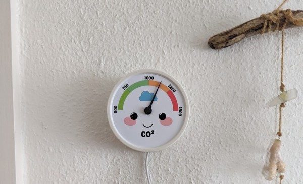
[Cyrill] has a good home automation scheme going: there are a number of physical switches set around the place that control the essential functions. The only problem is that in the winter time, this results in a great deal of phone checking as [Cyrill] tries to monitor the CO2 level. Tired of all this screen time, [Cyrill] set about to create an incredibly cute (and useful) Co2 monitor that plainly shows the current level and how bad it is, relatively speaking.

A large servo and an ESP32-S2 make up the guts of an analog CO2 sensor.

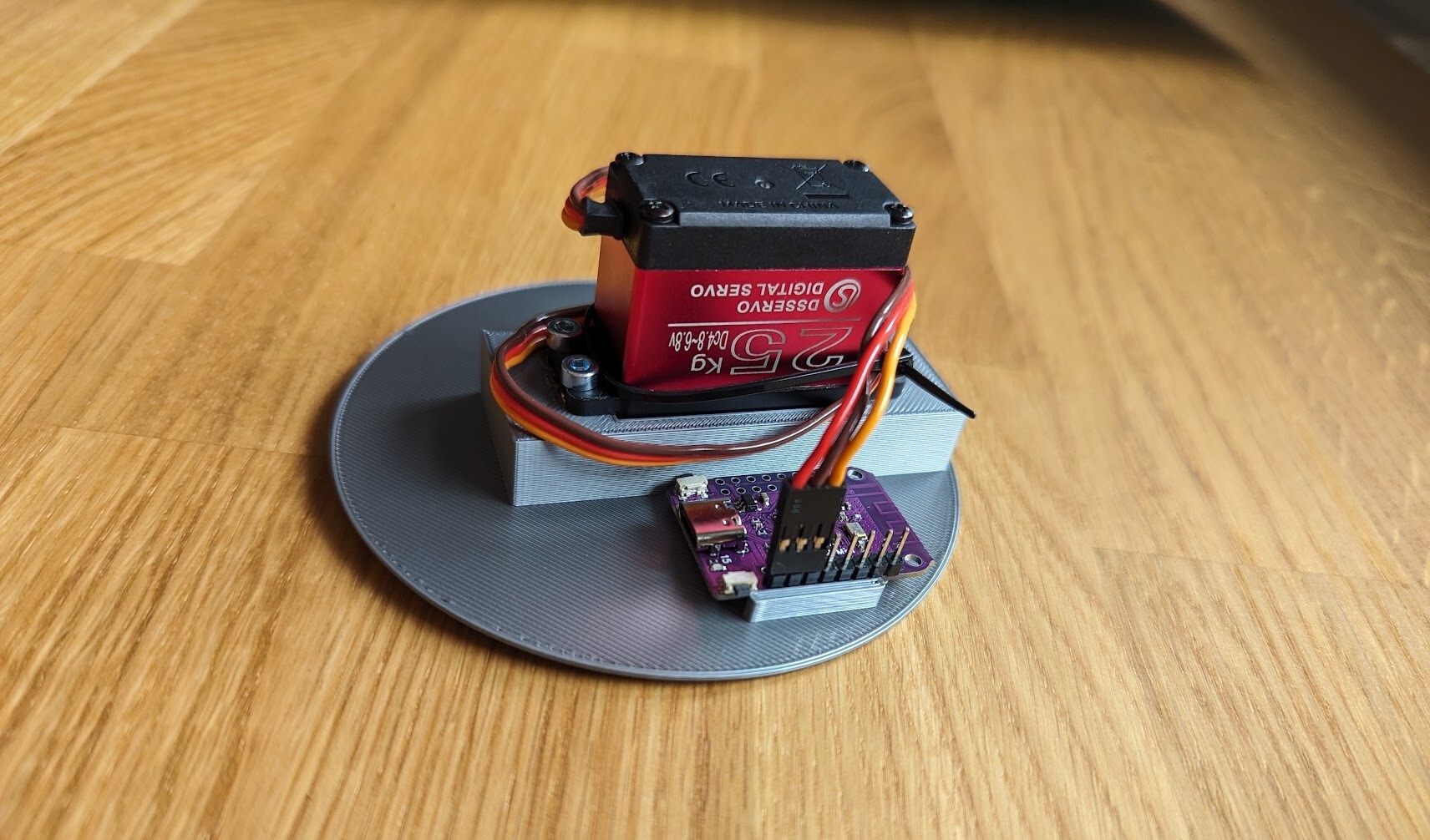
Behind that adorable face is a DS3225 servo being driven by a Wemos S2 mini, both of which [Cyrill] happened to have handy. Although the 25 Kg servo may be complete overkill for the situation, [Cyrill] reports that it is quieter than your average AliExpress alternatives, which makes it well worth it in our book. Then it was on to Inkscape to make the gauge itself. [Cyrill] says they’re an Inkscape noob, but that face could have fooled us.

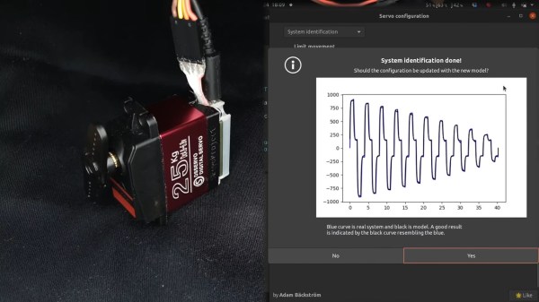
Finally, it was time to integrate it into Home Assistant to get readings from the CO2 sensors. This was easier said than done, but [Cyrill] does a nice job of explaining how to get the ESP32-S2 up and working.

If you’re out there monitoring CO levels in your home, beware of fake sensors that cropped up during the height of the pandemic and are likely still at large.

The modified servo being calibrated on the left half of the screen, with some graphs of its operation being shown on the right half.

Servo Surgery Teaches Us DIY Encoder Implants

Today, we shall talk about how [Adam Bäckström] took a DS3225 servo and rebuilt it to improve its accuracy, then built a high-precision robot arm with those modified servos to show just how much of an improvement he’s got – up to 36 times better positional accuracy. If this brings a déjà vu feeling, that’s because we’ve covered his servo modifications before, but now, there’s more. In a year’s time since the last video came out, [Adam] has taken it to the next level, showing us how the modification is made, and how we ourselves can do it, in a newly released video embedded below.

After ordering replacement controller PCBs designed by [Adam] (assembled by your PCBA service of choice), you disassemble the servo, carefully setting the gearbox aside for now. Gutting the stock control board is the obvious next step, but from there, you don’t just drop the new PCB in – there’s more to getting a perfect servo than this, you have to add extra sensing, too. First, you have to print a spacer and a cover for the control board, as well as a new base for the motor. You also have to print (or perhaps, laser-cut) two flat encoder disks, one black and one white, the white one being eccentric. It only escalates from here!

Continue reading “Servo Surgery Teaches Us DIY Encoder Implants”