[Avian]’s dad got a new ham radio transceiver with a 3.5 mm jack, and his pile-of-cables got him a headphone cable from Bose headphones. He built a DB9 to 3.5 mm adapter with that one – and it failed to let data through, outputting distorted garbage of a waveform instead. With a function generator and an oscilloscope, [Avian] plotted the frequency response of the cable, which turned out to be quite far from a straight line. What was up?
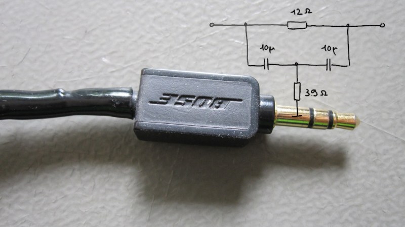
Taking the connector apart was a tricky job. A combination of blunt force and a nail polish remover soak didn’t quite get them all the way, so [Avian] continued to apply blunt force and took the jack apart with minimal casualties. Turned out that there was more to the 3.5 mm plug indeed — a whole PCB with a few resistors and capacitors, reverse-engineered into the schematic seen above.
Looks like Bose decided to tweak the audio characteristics of a specific pair of headphones, and an in-plug filter was, somehow, the most efficient solution. We probably shouldn’t expect to see this often, but it bears keeping in mind: next time your repurposed 3.5 mm cable doesn’t behave as expected, it would be prudent to do a capacitance test with your trusty meter or oscilloscope.
With how small MCUs have gotten, you can easily hide more than just a few capacitors! We don’t often see circuits built into cables, but when we do, it’s for malicious purposes.


This is pretty interesting, I’m actually thinking back to the times my cat chewed through my headphone wires, I replaced them but they never quite sounded the same after..
It probably won’t come up in a ham context, but Apple has made a few cables (e.g. Lightning) with ICs in them. As I understand it, Thunderbolt cables HAVE to have built-in electronics, which is why they’re so expensive; they’re not just high-spec USB cables, though you can’t tell by looking at them. I believe the original idea was to use optical fibers, but it turned out that copper conductors could work if you include circuitry in the cable to compensate for variations in capacitance and what not
No, they’re so ridiculously expensive because they got the official blessing from this toxic cult named Apple. Those chips are like a dime a dozen and they’re only there to prevent cheap knockoffs from working with their proprietary garbage. If you have ANY doubts about this then read up on the FW upgrades which “miraculously” made some of said knockoffs stop working.
FYI, if your comment doesn’t appear immediately, there’s no use trying to game the word filter as the system is likely to filter out your subsequent posts anyway. Just be patient, ok – we will get to your comment eventually. Removed the four subsequent nigh-identical comments of yours, figured it’d be prudent to let you know that you shouldn’t duplicate send them.
Okay, thanks. I truly hate such filtering systems from the bottom of my heart TBH.
We all do. I tend to try to figure out which of my words set off the moderation monster as well. It’s only half trying to game the system. The other half is trying to avoid it’s stupidity in the future by knowing what not to say. I hope no one really expects hackers not to try and understand why this website seems to randomly stop accepting comments, especially when you make a post with no links.
It’s like Dr. Skinner’s pigeons. When you’re being arbitrarily punished and rewarded, you become superstitious and develop weird rituals in attempts to control what is happening.
I’m going to have to write you up for stopping at four.
😭
I think you may be confusing two things. Lightning cables for USB are passive – no chips. Thunderbolt cables (nothing to do with Apple, although they do use them) require ICs.
“Lightning cables for USB are passive” – No they’re not. Just as I wrote above: they do use a chip in order to allow Apple to maintain their grip over this whole proprietary technology of theirs (I was talking about Lightning cables all along BTW). Check out e.g. https://www.techinsights.com/blog/apple-lightning-cable-teardown if you don’t believe me.
And what’s your problem with “to maintain their grip over this whole proprietary technology of theirs”?
The fact that it’s a monopoly, that it’s been made this way on purpose to lock out and stifle competition and thus it offers a greatly reduced set of compatible devices at a higher cost plus breaks compatibility too. Oh and also the fact that they can (and do) lock companies out of their ecosystem for completely bogus reasons too.
ASAIK The Chinese Lightning cable knock off has a 6 pin chip + 1 MOSFET. Likely the 6 pin chip is a microcontroller that emulates an EEPROM among other things. The MOSFET is for some power management.
FYI: picture of one such knockoff from EEBlog Topic: “OSHW Apple Lightning Connector?”
http://i.imgur.com/1xHX7wK.png
“Likely the 6 pin chip is a microcontroller that emulates an EEPROM among other things. ” – Yep and that’s what gets periodically invalidated by the iOS firmware upgrades.
Meh, that was 2012. I can’t recall actually having any problems with 3rd party cheap lightning connector devices. So it probably wasn’t that big of a deal after all.
“I can’t recall actually having any problems with 3rd party cheap lightning connector devices.” – Me neither as I’m not buying Apple devices.
“So it probably wasn’t that big of a deal after all.” – Maybe the Chinese have managed to completely reverse engineer their whole pairing process and replicate it in a way which Apple couldn’t fix with subsequent iOS updates, IDK. Either way the original intention was clearly to lock out everyone who didn’t pay the hefty Apple tax.
For the lightning cable it’s just an eeprom that tells the TriStar chip what to connect to the port (USB, serial, swd, …). There is no crypto involved, you can buy the same eeprom and copy the data from another cable. There are some Chinese chips that do this function and are very cheap.
MFI does use an actual chip with hardware crypto to authenticate that the peripheral is legit. There is also a possibility for software auth in some cases. See this project for some non-NDA info on the MFI chips: https://github.com/BertoldVdb/WACResearch
It took just one week after the first Lightning devices were on sale for cloned/bootleg cables and other devices to hit the market. Apple’s move to “assure quality” and create another monopoly market failed, like any such attempt does if someone cares to break it.
@CoolKoon said: “No, they’re so ridiculously expensive because they got the official blessing from this toxic cult named Apple.”
Amen. Anyone owning an Apple product is being taken advantage of. The puzzling thing to me is most Apple users know the products are hugely over-priced and locked-down to greedily prevent competition, yet they still line up like sheep to buy them anyway. I know of no other mainstream product like this. Calling Apple a “Toxic Cult” is putting it mildly. Then there’s Apple’s obsession with China and cheap forced labor. Do a web search on the words Apple and Uighur, or Apple and Xinjiang. Sheesh…
Being slightly evil and overpriced works in Apple’s favor.
When the users are forced to rationalize their own behavior, they invent compensating positive qualities and factors that justify the purchase, which aren’t actually true. Sure, the company employs child labor, but macs don’t get viruses! It’s “higher quality”, or “better design”, etc.
Once they start believing in those rationalizations, they become locked in because they start to believe it is actually the best product they could buy, or that the others are so inferior that they aren’t worth considering. Surely you wouldn’t ask ten grand for a handbag if it wasn’t really worth as much?
Lightning is not quite Thunderbolt though, is it? … We should write about this! I’ve seen some cool people doing things with Apple protocols for sure ^__^
That’s not a DB-9 connector. It’s a DE-9 …
He He, I never tire when this is brought up and I always say DB-9… :)
One can just say “x pin D-sub” to avoid the whole argument to be fair.
This is not new to Bose, my old earbuds have a little plastic enclosure half way through the cable with a filter to boost bass frequencies. In that case was obvious, having it hidden in the connector may be a little more tricky.
Heh, quite a tricky way of making their earphones sound better :) Not that I blame them, but still…
Trust is hard to earn and harder to earn back. Manipulation of the audio chain exemplifies and promotes mistrust. Just sayin’…
well, yes to some. However, most people are clueless and frankly, don’t care to be clued. If it works well, they just don’t care. Now, the Lightning cable lock-in is a different story and depends on your susceptibility to apple flavored Kool Aid.
How exactly is a passive filter any more of a manipulation of the audio chain than Bose’s design or selection of drivers for the headphones themselves? Both effect the experienced sound quality.
I’m pretty sure this cable wasn’t sold as a generic headphone cable, but was sold with a pair of Bose headphones. It may even have been hardwired to the headphones so never intended for use with anything else.
Was this a kludge on Bose’s part, to compensate for a bad design or inferior components? Or was it a manufacturing shortcut, where they reused a design but slapped a different cable on to change the sound for a different market?
This is probably more sinister than that.
In all likelyhood this filter was added onto the cable to make the original headphones sound terrible without the Bose original cable.
Not a last second fix, but a way to coerce customers to but replacement parts from you or buy new headphones when the old ones sound terrible.
We don’t know if the cable was hardwired originally and cut off a pair of broken headphones. Plenty of headphones have had hardwired cords.
Uhm…..any source/evidence for this?
I used to use chisels, saws and utility knives to remove molded on connectors. Dealing with cutting myself and damaging the connectors. Found one of these at a pawnshop (the plain multi cut tool). Does a much safer job and uses regular utility blades.
To re-assemble I use e6000 inside some shrink tubing. So far so good.
https://www.amazon.com/Ronan-Edge-3-Pack-Cutting-Tool/dp/B07ND6MJJ6
Putting a bandpass filter in their cable certainly is one way to achieve the old joke: “No highs, no lows – it must be Bose.”
Well, yeah, that’s what Bose is infamous for. Wonky speakers that are made listenable via EQ. Interesting they’re still doing it…and with headphones too!
And yeah, as mentioned…no such thing as a DB-9…
Yes, there are 9-pin Dsub connectors in a B size, so could be called DB-9. More commonly they are called DB-9W4. It has four high-current contacts and five ‘normal’ ones. Contacts for up to 40 amps are available. Made by Amphenol, Molex and Norcomp, at least. It’s fun to trot one of those out when a noob engineer specifies “DB-9”.
The really fun ones are 13W3 with the three coaxial connections replaced with tubing connections for fluid or gas, or higher volts/amps single wires. Thus a 13W3 can have small gauge wires for control, a couple of large wires for power, and an air or hydraulic line. Just the thing for connecting an EOAT (End Of Arm Tool) to a robot that uses an air actuated gripper – and you want to have a single connector to make R&R easier.
Yeah, I remember coax inserts in them too, but haven’t seen any retail lately (haven’t looked very hard though).
My old Sun Ultra had an S-Bus video digitizer that used them. Those cables were pricey stuff.
Here’s a DB9 connector:
https://www.cablewholesale.com/products/serial-modem-cable/db9-serial-cables/product-10d1-03206bk.php
It’s for connecting serial ports. Often seen before USB was introduced. Pretty ancient by today’s standards, but perhaps still in fashion on Ham radio equipment.
But as hinted by other posters, the ‘B’ indicates a large shell size (width) the same as a parallel port (DB-25). The smaller 9-pin plug should be called a DE-9, rather than DB-9.
Chapter and verse can be read at https://en.wikipedia.org/wiki/D-subminiature
The trouble is that people who’d gotten so used to DB-25 parallel and serial ports on PCs assumed that the smaller 9-pin variant must be called a DB-9.
It’s hard to “make out” what really happens here without the rest of the circuit, namely the output amp and headphone characteristics (Z, etc.). At least, that’s the way I was taught. For example, it seems that the 12 ohm resistor “blends” (shunts) L & R channels amplifier outputs and loads them too. Is this really just to save a resistor? That’s not “good” design, although admittedly, it probably won’t hurt the amplifier outputs nor affect the overall response much. But I don’t see any special spectral benefit for that compared to an ordinary dual-port low pass (the rest of the circuit). So maybe it’s my old eyes, but it looks like that other resistor to ground is 3.9 ohms? And again, it’s shared with both L & R channels. Again, probably unnoticeable, but then there are those who claim they can hear the differences in vacuum tube vs FET vs bipolar and even those that claimed they could hear the differences in gold vs aluminum CDs. So, someone please explain to me, how does this make Bose a premium sound equipment source? It seems the opposite.
“The circuit is symmetrical and has two identical parts for the left and right channel. ”
i.e. the channels are independent.
Even if their values were absolutely the same to 10 decimal places, if the L & R sides are different, which by definition they are (unless this is a monaural signal), they would have a different effect on the opposite side. “Being identical values” doesn’t make their effects independent. For that, you would need near-infinite impedance input amplifiers, not passives. OK, OK — no one would probably be able to (honestly) hear the difference, but I this supposed to be science or shooting the breeze? Why buy Bose equipment, or any “brand” then?
The L & R channels are independent. They are not connected together. There are two separate circuits. There are no share components, not even the 3.9 ohm. The diagram shoes one of two identical circuits, one for each channel. The two channels do not interact. This is plainly obvious from the text in the post, the photos, and the context.
Yeesh. Where’s the edit button, HaD?
If you say “This is plainly obvious from the text in the post, the photos, and the context.”, then I say we see (read) very different things. Nothing states there are two identical circuits, one for each side, neither explicitly, nor implicitly. There are no labels, the symbols used for terminations are generic, not an input and output arrow, so my assumption is that those terminal points are connected to the L & R channels of the audio output AND the L & R channels of the headphone.
But, IFF there are two identical circuits, then you are right, there should be no interaction, other than possible crosstalk and PSRR noise (and their analysis is greatly simplified). I’m sure the author could clarify the ambiguity. If I saw this at a HW design meeting at work, I would ask that question rather than assume something on faith. I worked on ground-based navaids, so getting it “right” was critical, so I’m biased regarding details, and there has never been a aeronautical accident attributed to ground-based equipment (e.g. ILS at an airport), at least one designed and made in the USA (not a slight to other sources, but I never got input on those).
I’m OK with it being either way, but the single circuit’s behavior is not identical to two individual circuits, right?
First off, this is a stereo audio headphone plug. There is no reason to believe the two channels would be connected together through this circuit.
You say: “Nothing states there are two identical circuits, one for each side, neither explicitly, nor implicitly.”
From the post: “The circuit is symmetrical and has two identical parts for the left and right channel. Each half consists of 2 multi-layer ceramic capacitors and two chip resistors. “
And the photo likewise shows a circuit board with four caps and four resistors — two of the described circuits.
There are two independent, identical circuits. There is no ambiguity here.
Would two identical schematics side by side be less confusing? If so, staring at it cross-eyed could help.
Sorry, MY BIG BAD! My comments were based solely on the Hackaday article. After I couldn’t find “symmetrical” in the Hackaday text, I FINALLY went to the embedded source link and saw all the references you were pounding me on. I don’t do that as a rule, but I got sloppy this time which resulted my confusion (so now I can clearly see yours). AND, that source article is really good.
What Bose did doesn’t exonerate them. If they needed to fix the headphone’s response, it should have been done inside the headphones, and not externally in the cable. It gives new meaning to “use OEM equipment only”.
It reminds me of the my first Sony camera that had a “smart” battery that would only work with Sony batteries (and the “smart” drained the batteries to exhaustion, killing the cell even if you removed the battery from the camera for storage!), or those obnoxious Epson printer cartages that they got class action sued over, or… on and on!
Again Paul, sorry. And Avian, nice article! (my head’s down)
see kids, cables do make a difference /s :)
That says maybe, but I’m still gonna make fun of the $1000 1 meter “audiophile quality” ethernet cable… :P
You’d be better off making some $1000 1 meter “audiophile quality” ethernet cables, and selling them!
I had a similar problem with a Pebble watch charging cable. I had a box of ’em, and had snipped off the proprietary end of one to use as a plain 2-conductor USB power lead to power an Arduino circuit. Worked fine unless the power supply cycled. No problem when I plugged the USB into an active supply, but if I left the USB connected and switched the supply off and on, it would refuse to boot. Tried a bunch of different phone chargers etc, same result. I was pulling my hair out!
Turned out, since the watch charger used exposed pogo pins, there was a little over current protection circuit hidden in the USB connector. I’m not sure exactly why the order of operations had such an effect, but at least I got the dang thing working…
Looks like protection against DC
I should make a high pass filter adapter to lower bass frequencies.