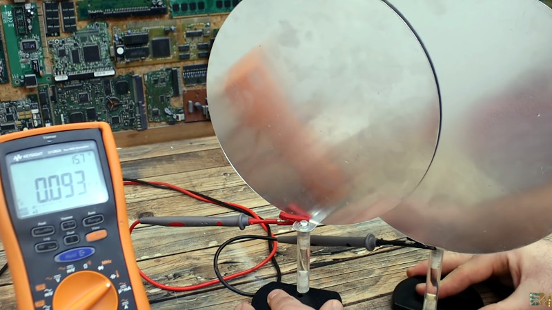
Of course, we all know that capacitors are conceptually two conductors separated by a dielectric of some sort. But outside of air-variable capacitors you normally don’t see them looking like that. For example, a film capacitor has its plates rolled up in a coil with an insulating film in between. You can’t really see that unless you take them apart. But [Electronoobs] makes some giant capacitors using large plates and does a few experiments to demonstrate their characteristics. You can see his work in the video below.
The arrangement reminded us of a Leyden jar except there’s no physical motion. He also had some entertaining footage of electrolytic capacitors exploding when connected backwards. The reason, by the way, is that electrolytic capacitors have conductive goo in them. By putting a controlled current through them during manufacturing, a very thin insulating layer forms on one electrode. The thinner the layer, the higher the potential capacitance is. The downside is that putting current in the opposite way of the formation current causes catastrophic results, as you can see.
The value of a capacitor depends on the area, the spacing, and the type of dielectric between the plates. The video covers how each of those alters the capacitor value. Real capacitors also have undesirable characteristics like leakage and parasitic resistance or inductance.
It used to be that capacitance meters were exotic gear, but these days many meters have that capability. This would be a great set of experiments for a classroom or as the basis for a kid’s science project. For example, measuring different dielectric materials to determine which is the best for different purposes.
Granted, capacitors are pretty basic physics, but it is easy to get wrapped up in using them and not think about what’s going on inside. This video is a good introduction or a refresher, if you need one. It is easy enough to make your own variable capacitors or even special capacitors for high voltages.


Very good presentation for beginners.
They should take care that SMD capacitor line marking is for ++++
Nice demonstration. I’m reminded of a variable capacitor I encountered in the 1980s. In a Cipher streaming 9-track magnetic tape drive that used a spring-loaded arm to measure the tension on the tape, the position of this arm was measured using a variable capacitor that consisted of two fixed square metal plates about 2mm apart, with a plastic sheet connected to the tension arm, that slid between the metal plates. Because the plastic had a higher dielectric constant than air, moving the arm moved more of the plastic sheet between the plates, and changed the capacitance, which was measured by a simple circuit, just as shown in the video. This was much more reliable than a potentiometer, because potentiometers rely on mechanical contact between a slider and the resistive material, which can produce noise as the slider bounces onto and off of the resistor as it moves. This would be a serious problem in the tape tensioning system, since it could easily break the tape if the servo system that provided the tension was presented with noisy feedback. I never saw one of these drives break a tape. These tape drives also had an ingenious way of synchronizing the signals between the nine channels, but that’s a whole other story.
My current long-term project (5 years and counting…) uses a capacitor very much like the one in the article.
Here’s a puzzle for you:
Suppose one side of the capacitor in the video is grounded. Close together, the capacitance (to ground) is a constant times the plate area divided by the distance – about 120pF for a 3mm gap with a 220mm disk. Double the distance, and capacitance is halved. Double it again and the capacitance is 1/4 the original capacitance.
How far do I need to move the plates to get the capacitance below 5 pF?
(Note: The answer is not obvious.)
Second puzzle:
The dielectric polarizes, which imagines molecules as charged barbells rotating, which presents the charge on one plate closer to the other plate. IOW, if you stick a 1cm thick piece of glass between the plates, glass with a dielectric constant of 5 will present one plate as if it were 1/5 the distance away, effectively multiplying the capacitance by 5.
This is because when the barbells rotate to align with the field, when the positive side of the barbell points to one plate there is a negative side that’s presented towards the other plate. The negative charges on the plate are therefore “translated” closer to the other plate.
Why is the dielectric constant *constant*? Why isn’t the charge polarization “springy”, in the sense that a low voltage will polarize the charges a little, and a larger voltage will polarize them more?
As a final note, the dielectric constant isn’t a scalar, it’s a vector. It has both a real and imaginary component.
In calculations we always use the imaginary portion, which tells us the change in capacitance when using the dielectric, but there’s a real component as well, which tells us how much energy is dissipated in the dielectric (the dielectric can get hot).
All this came up in my project, that I’ve been struggling with for years, that involves pushing 600 watts through a capacitor much like the one in the video.
Capacitance is easy to calculate, but reality is not so simple.
How far up from the ground are the plates?
Isolate the plates as much as you like, then attach one plate to ground using a wire.
For example, hang both plates (use a non-conductive plate holder) in the middle of an empty room, connect one plate to ground, and measure the capacitance between the other plate and ground.
You didn’t specify the room. A conductive object inside a conductive shell will exhibit capacitance proportional to the average distance between all the surfaces.
>Why isn’t the charge polarization “springy”
What would it spring against?
Charge polarization is essentially moving charges away from their lowest energy position, so they would experience a force back to that position except that the force of the field attracts them out of it.
If the field force is increased, why don’t the charges move further away, resulting in larger dielectric constant?
True, but you were talking about rotation of dipole charges.
>If the field force is increased, why don’t the charges move further away, resulting in larger dielectric constant?
Are you wondering whether it happens at all? Most real capacitors do exhibit voltage dependence.
Theory often assumes the forces at the middle of infinitely large plates… however, our spherical chickens have edges, and when the distance between them is an order of magnitude or two smaller than the plates, they behave somewhat close to theory, but when the distance becomes closer to the same magnitude as the plates, all polarization paths are not straight and funky stuff happens.
Then also you get additional physical effects coming into play as voltage is raised and it’s blowing ions off all the corners and sharp edges.
Disc plates have “self capacitance”, check the Wikipedia page for info. It’s essentially the capacitance of one plate to “the rest of the universe”: the edge of the universe is very far away, but there’s a lot of it and the effects almost cancel but not quite.
The self capacitance of a disc is 8*pi*E0, which for the values specified is about 7.75 pF. It’s impossible to get the capacitance of a 220mm disc below 5pF regardless of how far away the 2nd plate is.
Roughly speaking, self capacitance becomes dominant when the plates are further apart than their diameter. The electric field is then no longer uniform and constant for the non-grounded plate.
NASA has problems with capacitors too: https://www.nasa.gov/sites/default/files/atoms/files/nesc_tb_15-01_preventing_incorrect_installation_of_polarized_capacitors.pdf.
According to that document, there are tantalum capacitors in operation on the ISS that have been fitted backwards, “but have not yet resulted in failure” because NASA over-specs the voltage ratings.
“It used to be that capacitance meters were exotic gear…”
Not really. I think people get stuck thinking that and didn’t try. When I was in high school in the ’70s, I designed an accurate capacitance meter using two 555 timers. I built and sold a fair number of them. I still have a prototype an schematic from when I started building them to use a DMM as the display rather than a built-in analog meter.
I’ve used them for all kinds of things including fluid level, moisture sensing in soil with insulated sensors, capacitive sensing of people/hands from a distance, capacitive switching, and more.
https://hackaday.io/project/183405-dual-tlc555-capacitance-meter-01pf-resolution
The analog meter version used a 50uA meter and was readable to about 0.5pF on the lowest scale. The version using a DMM used the 200.0mV scale and was stable to 0.1pF resolution. I experimented with making that 0.01pF resolution, but there was no real point to that as merely moving your hands within a few feet of the meter and capacitor would change the readings.
I did use that effect for sensing a person or their hands from a foot or more away. It involved using the capacitance sensing charge/discharge curve through an Op Amp to drive a shield behind the sensing plate, to reduce the effects of parasitic capacitance behind the sensing plate.
In 2012 i worked in a fish cannery at the very end of the line. The department I worked in was where 1200 lb metal carts would come out of the pressure cookers and be cooled down, then the crew i worked on would “rack” the cans off the carts to be stacked on pallets.
Each cart had 7-10 layers of cans on it, each layer seperated by a mesh sheet made out of aluminum or plastic. As we would rack the cans off the cart, we would stack these sheets on an empty cart, which when full would be sent back to the canning department to be reused. Often throughout the day when putting a sheet on that cart, I would get a strong static electric shock (strong enough it would jump several inches) and hurt like hell.
I realized that the alternating layers of aluminum and plastic sheets were creating this electric charge, then when grounded to my hand would deliver the shock.
This post reminded me of that.