If you haven’t seen [Ken Shirriff]’s teardowns and reverse engineering expeditions, then you’re in for a treat. His explanation and demonstration of the Apollo digital ranging system is a fascinating read, even if vintage computing and engineering aren’t part of your normal fare.
The average Hackaday reader should be familiar with the concept of determining the distance of a faraway object by measuring how long it takes a sound or radio wave to be reflected, such as in sonar and radar. Going another step and measuring Doppler Shift – the difference in the returned signal’s frequency – will tell us the velocity of the object relative to our position. It’s so simple that an Arduino can do it. But in the days of Apollo, there was no Arduino. In fact, there were no Integrated Circuits. And Apollo missions went all the way to the moon- far too distant for relatively simple Radar measurements.
How could range (distance), position, and speed then be measured? The answer is one that [Ken] aptly describes as fractal: Each layer of complexity hides beneath it another layer of complexity. Using equations dating from 3rd century China as well as cutting edge weak signal telemetry, Apollo engineers devised a complex but workable system that used an S-Band transponder to take data transmitted from a powerful ground station and send it back on another frequency. One great hack was to use Phase Modulation to encode the downlink instead of Frequency Modulation so that Doppler data gained on the uplink wouldn’t be lost on the downlink.
By knowing the precise position of the ground station and the very large parabolic antennae, not only could the distance and speed be measured, but a good estimation of the spacecraft’s position in 3d space could also be had.
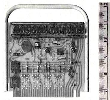
From the use of delay line memory to aggregate weak signals to a state machine computer made up of discrete transistor logic, all the way to the cutting edge transponder on the Command Module, the Apollo digital ranging system is an excellent example of great hacks coming out of a program with tight technical constraints.
We highly recommend giving [Ken]’s blog a read and be sure to check out the interactive demonstration web pages he’s put up to help us grasp the genius of the Apollo engineering teams. [Ken]’s been featured on Hackaday a number of times reverse engineering such diverse things as a Yamaha DX7 Synth chip.


So. Many. Little. Coax. Connectors!
and none of them Color coded!!!
And every one is a failure point.
Wow! that is… far out!
At the end of the day, it was just a math problem.
Only the calculator was a slide rule!
Something like this would be very cool for accurate terrestrial navigation without satellites. GPS is cool and all but it’s pretty insane when you consider the infrastructure, and somewhat sensitive to the weather.
Seems a bit like an upside down GPS system.
@GageJ … well the FCC has a database, co-ordinates and transmission powers of all TV stations in US, and you can get USB dongle TV frequency sticks that worth with GNU radio (don’t think it matters you can’t decode ATSC to a picture using Euro sticks)
@RW, hmm… are you suggesting a system that can receive TV signals, triangulate between two stations using RDF and relative signal strengths, then decode the station ID’s, and look them up in the FCC’s database so it can perform trig to convert its distance and angle from TV stations into coordinates? because that would be really cool…
Yes, or you can do it with FM stations, the antennas get a bit cumbersome though… and it’s likely to only tell you what ballpark you’re in, if you do it well…. plus there’s signal reflection and tropo scatter problems.
You can also manage it with an AM receiver when you’re at sea, but it only gives you a few square mile fix… which used to be pretty good if all you had was dead reckoning to go on otherwise.
All those radios sold to small craft owners with an antenna that can rotate. They were aimed at that use.
It all makes sense in concept but when you get down to how it’s done using analog circuits, RF is voodoo.
It’s also the “glitter = craft herpes” of electronics, gets everywhere.
We had a term for that in the Navy. We called it BFM. Black F****ing Magic. 😀
In the normal NASA redundant manner, they also had a microwave C-band (4.5GHz) radar system for tracking missile tests, and improved it for use with Apollo at lunar ranges. The design team i joined in 1966 made a mod-kit for our FPQ-6 pulsed radars to add Coherent Signal Processing (CSP) that added Doppler velocity tracking to the radar, with a whole new transmitter. It skin tracked, or tracked a coherent C-band transponder, and did spacecraft acquisition to start the tracking. Tight Doppler frequency control allowed narrow band IF crystal filters to reduce tracking noise in the 4 axis tracking servo loops (Range, Az, El, Velocity) and the system computer resolved the Range-rate vice Doppler-velocity ambiguity. To acquire the target velocity we used a received I&Q sample time compressor and correlated with ambiguous velocity & acceleration profiles; using p-mos serial shift register memories 16, 32, or 64 words long, with the rest of the DTL logic. The angle tracking loops were integrated in the computer software, while the sigpro hardware tracked the range & Doppler, at 160, 320, or 640 PRF.
I really enjoyed the article about the Unified S-band Tracking and Communication link.