Electric vehicles (EVs) are something of a hot topic, and most of the hacks we’ve featured regarding them center on conversions from Internal Combustion to Electric. These are all fine, and we hope to see plenty more of them in the future. There’s another aspect that doesn’t get covered as often: How to charge electric vehicles- especially commercially produced EV’s rather than the DIY kind. This is the kind of project that [fotherby] has taken on: A 7.2 kW EV charger for his Kia.
Faced with spending £900 (about $1100 USD) for a commercial unit installed by a qualified electrician, [fotherby] decided to do some research. The project wasn’t outside his scope, and he gave himself a head start by finding a commercial enclosure and cable that was originally just a showroom unit with no innards.
An Arduino Pro Mini provides the brains for the charger, and the source code and all the needed information to build your own like charger is on GitHub. What’s outstanding about the guide though is the deep dive into how these chargers work, and how straightforward they really are without being simplistic.
Dealing with mains power and the installation of such a serious piece of kit means that there are inherent risks for the DIYer, and [fotherby] addresses these admirably by including a ground fault detection circuit. The result is that if there is a ground fault of any kind, it will shut down the entire circuit at speeds and levels that are below the threshold that can harm humans. [fotherby] backs this up by testing the circuit thoroughly and documenting the results, showing that the charger meets commercial standards. Still, this isn’t a first-time project for the EV enthusiast, so we feel compelled to say “Don’t Try This At Home” even though that’s exactly what’s on display.
In the end, several hundred quid were saved, and the DIY charger does the job just as well as the commercial unit. A great hack indeed! And while these aren’t common, we did cover another Open Source EV charger about a year ago that you might like to check out as well.


Using software (let alone an Arduino) for RCD operation is very dangerous. If the software hangs for any reason then goodbye RCD!
Adding in a watchdog would help, but I’d still be very nervous around this.
You could drive the relay control circuitry with an AC-coupled signal (and some sort of peak-hold circuit). The idea behind this is that you’d need to keep toggling the relay pin to keep the relay engaged – if the pin stops toggling (due to hung firmware) then the relay would release.
Sent this to a friend who is a forensic fire investigator with EE background…
“Most RCDs are ‘software’ nowadays; tiny little processor does A2D and then trips on the fault. Open up an RCBO and look inside.
“But, this guy broke the law – you are not allowed to put your own design inside a branded box (I’d hammer him in a legal case; remember, that is the type of work I do). The second part is the relays are not allowed to be single pole devices; the two must be interlinked (if the Live relay went short and stayed that way, the circuit remains live and does not protect). This guy tried to save a few £, but could land up being sued blind. The warranty on his car is also now void.
“Oh, and another thing, the RCD function is not legal either; it is meant to be a Type B i.e. able to detect AC, rectified AC (half and full wave), high frequency, and DC (battery feedback from the vehicle). Another law broken. Double stupid mistake.”
I suggested RCBO at the fuse box instead. His response:
“RCBO not allowed, must be 2-pole Type B RCD (RCBO only trips the Live pole leaving Neutral connected; lose the Neutral and all hell breaks loose – same applies to Solar PV installations)”
Now ignore the comment about warranty as I know where we are. And we can split hairs about the legality, etc.
But the rest from a safety background is super important – especially when HaD says “[fotherby] addresses these admirably by including a ground fault detection circuit”.
It’s easy to criticise, both the original post and the criticism. Hopefully, there is something to learn from both sides.
Yeah, leaving RCD to off the shelf certified items is deffo a wiser choice IMO.
Cool project though.
It works great, until it doesn’t. I know someone who bought an off the shelf commercial charger from a lesser known company that eventually ended up overheating in a big way, destroying his car’s charging port resulting in something like a $3500 repair. The manufacturer did right and paid for the repair and presumably worked on their product some.
The point is, if someone trying to make a living selling these stumbles, there may be more to charging than meets the eye. It is a nice hack, and for £ 900, possibly worth the risk, but go into this hack with open eyes.
How would a wallbhbox overheat your charge port?
That sounds very suspicious, also 100% of the EVs I know monitor the charge port temperature and stop charging at certain thresholds.
They used a crappy connector or did not detect it wasn’t inserted properly and sent the full amps. This result in the charge port of the car damage. Charger side too..
All EVs worth their sort monitor the charge port temperature. Tesla have thermal pads pushed against the bus bar connected to the current carrying inputs coupled to a thermocouple (to the MCU) AND a thermal switch (that disconnects the pilot signal, aborting the charge from both sides of the cable).
“Faced with spending £900 (about $1100 USD) for a commercial unit installed by a qualified electrician, [fotherby] decided” that he’d rather risk putting his house on fire and have his insurances show him the finger when he requests damage coverage.
This is pretty much the reason why things like that should be done by qualified electricians with certified hardware. The commercial unit has a lot less risk of causing a fire. If the fire is caused by a defect in the charger, the manufacturer is liable. If it’s cause by improper installation, the electrician is liable. They have their respective insurances for things like that.
A self-made and self-installed solution burning your and your neigbours house down? Tough luck.
And that’s how they continue to justify price gouging for something that is actually relatively simple. This had *nothing* to do with the quality of the installation or of the device itself; plenty of crap electricians and shitty commercial devices out there that will happily burn down your home as well.
The only thing this changes is increasing the risk of an insurance denial *in the unlikely case* of a fire. Insurance companies will also still happily screw you over even if you do everything “right”, if they can justify it.
Well, it is already good that he informed himself about the dangers and protection mechanisms.
What is not so good is that he seems to have decided on his own what protection was adequate.
Unfortunately, what is adequate is not always enough to be legal, such a a Type B RCD.
Not only for this device, but for the entire upstream. There can not be a non-type B RCD upstream as otherwise there are circumstances the RCD won’t trigger.
Type A is adequate if pen fault detection is in place un the charge box. For second hand vehicles I think this option, if done correctly is a fantastic idea. Obvs get a spark to install etc… but why not let the tinkernerds have a slice of the pie?
This is hilarious. When the house burns, you will find the electrician long gone.
When the house burns, their homeowners insurance company will point at the not-UL-certified equipment and laugh
More relevant to this comment chain, if the homeowner has a licensed electrician install the charger and it burns the house down, the homeowner gets the payout and then the homeowner’s insurance, the electrician and the charger’s manufacturer get to fight over liability, depending on myriad factors, including the investigation report, whether the manufacturer is still around and how good everyone’s lawyers are. If the charger wasn’t UL-certified (an extremely unlikely event), that’s on the electrician, not the homeowner, and the electrician would be quickly and successfully sued by the homeowner’s insurance firm. The electrician wouldn’t be “long gone” because corporate lawyers have a long reach, and limited liability would not shield the (hypothetical) electrician.
Recouping the money would be especially easy for the homeowner if they properly alerted their insurance and, if relevant, lender of the improvement being made.
Now, outside of this comment chain, and talking about a charger such as the one in the article, you are 100% right.
And regardless of how long gone the electrician and manufacturer are, if he’s got it installed by a professional electrician, he’ll have the paperwork to prove it to his insurance company, so they’ll pay out, and it’s up to the insurance company to try to reclaim it from them.
If your conection causes a short and burn your house down and if they find that you wired it illegally you are out of luck and you won’t get paid a penny. Penny wise pound foolish. To me it is not worth the risk.
While I admire the project … designing this for sake of saving money is risky for both human electrocution and fire.
At 1100 USD you buy insurance peace of mind.
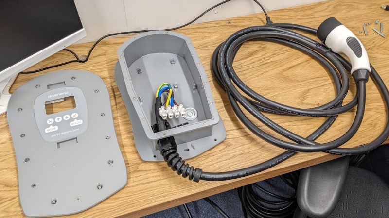
Those screw terminals are certainly not “pro”.
7.2kW at 240V is 30A (I only see 1 phase coming in; blue, brown and yellow-green). Those relays seem rather small for 30A, we can’t see the PCB traces but those need to be beefy for 30A, and the screw terminals also seem rather flimsy.
If he’d used a proper relay, with screw connections, it should all be fine, as the crappy screw terminals he used now wouldn’t have been needed, and the current wouldn’t even run through the PCB.
If you bothered to read his article before you commented you would see that most of what you said are assumptions.
The relays are 40A, and he does show the PCB traces.
According to the datasheet, the open contact distance of these relays is “>1.8mm”.
I don’t know about the specifies of his country, but in most European countries, 1.8mm is not enough if used as the main interuptor for a circuit. So I doubt these relays were a good choice.
If you’re going to be an unpleasant person about it, at least ensure you’re right. The datasheet says the relays are only rated for 40A at 30VDC resistive load, and at 250VAC they are rated for 35A *resistive load*.
Does a EV charger look like a resistive load to you?
I’ll give you a hint: inrush current.
A low cost but very robust and reliable alternative would be a contactor of the type commonly used in HVAC equipment. It would also eliminate the need to run high current through the PCB. Get one with a 120V or 240V coil to make it trivial to control with a SSR.
The resistive load part is only for when “hot switching”, preventing arcing from inductive loads at high current. The EV will have stopped pulling any current when the contacts are open (even in the RCD trip case, as the MCU pushes the PWM duty to 0% and the relays take 20ms to open).
Internally, many EVs have an inverter that charges up the capacitors before closing contactors. Before closing the HV battery contactor using the 12V battery to match the HT voltage to protect the car’s HV contactor life, so no current flows when connecting. On the mains charging side such is relevant here, there’s a soft-start resistor in series with the capacitors to limit inrush current that is bypassed once the capacitors are charged. This saves the diodes on the input bridge rectifiers and the charger’s contactors. I’ve designed very similar things professionally.
I’d rather use an installation contactor. (And a proper RCD…)
And I’m not very fond of these crappy terminal blocks either…
But maybe I’m spoiled by living in germany, where these things seem to be handled rather more professional….
I like the idea but as other have mentioned the Arduino RCD scares me a bit.
A more appropriate option would have been a commercial RCD which is guaranteed to switch at the appropriate current and time with the regulated flash over mitigation etc and not likely to lock up after a software update. IN conjunction with his switching circuit
Software RCD?! Nope… I love hacking together stuff but there’s stuff I want certified working 100%.
I want to know why you can’t buy the charger interface and install it yourself. Was considering a plug-in hybrid, and putting the charger on the side of the house. DW says “we have to pay to have that installed.” Nonsense, I was installing stage lighting systems for years before I met her. I’m on good terms with electricity and how to install it. It’s not considerably different than putting in a dryer circuit here in the US. Not sure why they don’t sell DIY chargers for install. That way the relays and electronics are tested and all you’re adding is the power.
But liability, liability, liability.
The inability to have a plug in with AWD is what cancelled the plug in hybrid idea.
They do, search for plugin EVSE. All you have to do is install an outlet.
They do sell DIY chargers you can install yourself, both hardwired and ones that plug into dryer outlets. Just do a search on Amazon. $250 for a chargepoint smart charger one.
$250…..I freakin’ wish. ChargePoints are now running up to $1k, and we’re never lower than $699.
Just came back from a visit to his page….Not a fan of the solder job on the relays.
I applaud the effort into making this unit safe with the GFI, but I have some real issues with the soldering on the board — some very bad connections.
The soldering of the mains wires to the board is truly worrisome. The lack of strain relief even though it’s inside the enclosure is also an issue for me.
I think the current iteration is a potential hazard. I do believe most of the issues are correctable and I hope the builder takes an objective look at this after seeing the comments here and fixes the device.
Personally I would have also gone for a SSR with screw terminals not soldered mains — The mains shown on his board violate on of the cardinal rules I was taught when I learned to solder. First make a good mechanical connection.
I also don’t believe soldering is the best for a switch load like this — just a minorly flawed connection and with that power level the heat generate could melt and loosen those mains. Also too many connections (potential failure points) on the mains.
Doing safety critical stuff in firmware is certainly possible, but I cringe if the word “arduino” is used within 20km of such a project. The arduino board seems to be pretty solidly soldered onto the mains PCB, but such add-on boards should not be in projects like this.
One of the advantages of software is that it can check itself.
For example, you can put an extra wire through the current transformer and then generate a fault current on purpose and check if your fault current is actually reported back by the current transformer & amplifier. Apparently this is incorporated in the project, so that’s a plus point.
I also do not understand the prices of these things. Pricepoint is probably so high just because they can ask it, under a vague claim of liability and insurance paperwork (Which does make some sense, but does not really justify the price point) Even this guy paid 120 pound for an empty box that should not cost more than EUR10 or so.
I do not like the Idea of PCB relays for such high currents. A nice beefy contractor on a DIN rail would be much more appropriate for a home built version.
Also, uC’s and a few opamps are cheap. Putting in two sense circuits and have them check each other is not too difficult to build, and it’s a quite common way of doing things for safety critical stuff. Those bright yellow PLC’s also used to be horribly expensive for no particular good reason. Both the “industrial” robustness, and the “safety critical” part add a bit to the cost, but most of the added costs are probably just because you have to buy the stuff anyway.
For lots of stuff in industry, price is not very important either, 20+ years reliability with no maintenance is usually much more important.
Also, Mike Harrisson has taken some of these things apart. Making a comparison may be nice.
Aliexpress 32A (7kW) portable EV chargers ( EVSE ) Zencar, Khons
https://www.youtube.com/watch?v=jT8IsAd9ea0
The insides of the Aliexrpess box seem to be pretty similar.
And there are probably also plenty of other video’s about these things floating around.
Whether it’s legal to make and install such stuff may depend on the country you live in, but in the end it is not much more then a relay, a simple pulse generator and an RCD (which has no stamps from any supervisory aouthority in this case).
Original cost £900, saved a couple of hundred i,.e £200, so total cost £700, an open EVSE kit that is designed for the job and is open source with a proper enclosure and safety features is £335 inc vat shipped. built mine a year ago and works beautifully.
You can find EVSE charger 230v 7kw for 400€ on Amazon, including the type 2 plug, why on earth would we spend more for a less safe device?
No idea, for me personally it was the open source and community group of the OPENevse and the fact it had MQQT support and up-gradable.
I have no doubt that the insurance companies scour hackaday articles and comments looking for evidence to deny claims and cancel policies. Small effort, big reward.
The lack of a LM555 is disturbing.
+++
Why not just build an OpenEVSE?
Because you will void your vehicle warranty and your homeowners insurance and probably the local electrical codes. The local electrical inspector will rip it out and confiscate it and write you a ticket with a big fine. I have seen electrical inspectors declare a house to be uninhabitable due to code violations. Your insurance company will drop you and blacklist you. Don’t. Go. There.
But…it’s the same for his DIY box.
In the UK?
Because this charger does not meet safety requirements
I opened my commercial charger up to see what was inside and it has a raspberry pi mini. With that in mind this is clearly a great option as it uses very similar equipment.
First off there is no such thing as a “raspberry pi mini”, I assume you mean zero or zero 2 or maybe a compute module. Just because a commercial charger happens to contain a raspberry pi doesn’t mean that using an Arduino for a DIY car charger is a good idea, it is a hobbyist board. The pi is probably just there to collect usage data or to allow it to be controlled over wi-fi, and I would be very surprised if the PI was actually involved with the charging other than telling it to switch on and off. The commercial charger will have been properly designed and tested and pass all necessary regulations so to compare it to this diy solution just because it contains a pi is a bit stupid.
It’s weird that a lot of people here recommend installing a “proper” EVSE, when sometimes they’re the worst offenders:
https://www.mastrogippo.it/2019/07/design-decisions-and-competition-tesla-openevse-redacted/
Thank you for all your comments. Here’s a summary of what I have learnt from you all:
1) The soldered connections on the PCB are inadequate – Ok, I agree with this. A 40A terminal block would be much better. I should have done that. Is there any appreciable risk of those solder joints melting before the 50A MCB trips? I took some thermal image pics of the system operating with a 30A and there are no hot spots in the solder/wiring/connections. (Will add these images to the write-up this evening). The flimsier looking terminal block actually came with the Zappi enclosure so it implies the terminal blocks are appropriately rated.
2) Bad choice of relays – according to the datasheet, the relays used in this project are for EV chargers and can handle 250V 40A. EV cars soft start/stop their charging so the relays don’t have to connect/interrupt under load unless due to a fault condition. If you look at teardowns of some commercial chargers (eg. Zappi) you’ll find separate L&N single pole relays just like I have used. But, I agree having a dual gang relay so the L&N are mechanically linked does sound better. I have measured the power factor of the car charging (albeit when charging from a 13A socket) using a plug-in power meter and it reports a power factor of 0.95. So I think the car does present a resistive load. Logically, car manufacturers must have to ensure their onboard SMPS chargers have good power factor else the extra currents would cause problems in domestic setups, I agree.
3) Unsafe to use an Arduino (ATMEGA328P). I think you technically need special authorisation from atmel to use this chip for automotive or safety critical applications. I like the suggestion of incorporating a watchdog timer to guard against hanging. I’ll add that. And I like the suggestion [steaky] of having to regulaly toggle a pin purposefully to maintain engagement of the relay so they’d open by default during an error. Is that actually done in commercial chargers? It’s not done by the EVSE. If an unexpected reset occurred the relays would open in this implementation.
4) Should be a type B RCD – I think this is the main point from everyone. That the RCD functionality is inadequate. I essentially copied the EVSE RCD design, which I thought was a acceptable approach. What do people think of the EVSE RCD? I’m interested in the ability of commercial chargers (which also use a current sense coils) to be able to detect DC faults, because transformers don’t pass DC… I’m going to look into this. If a very slowly increasing DC fault current was to develop (not sure how this would actually happen) then I don’t think this RCD or the EVSE RCD would detect it.
Thanks for all your comments. I’m taking them onboard. There are some grey areas here. Several things have to occur to present a hazard.
1) You can get relays that have the switched side as wires or terminals. This way you don’t even have to worry about soldering, spacing, or PCB current capacity.
2) You’d have to do a fuller analysis of the commercial offering to see if there is a mitigating factor to their design that precludes the use of linked relays. Or maybe they were designed to an earlier standard?
3) Jack Ganssle does a good tutorial on watchdog timers. If you are using something for safety then it better be good. Again, it depends on the operation of the watchdog timer as to their suitability, so that’ll need further scrutiny. Regarding AC coupling the relay control, I’ve used this in the past in safety critical projects.
4) The ESVE is a US project, so it wouldn’t come under the same technical scrutiny as UK designs. In this instance, you’d come under BS 7671. There was an amendment in March 2022, so if there were a section on the ESVE for UK people, I doubt it would be updated that quickly. Again, I’ve not read BS 7671 so unsure of the actual wording. The way you are currently doing it is definitely wrong, unsure if the TypeA + 6mA is sufficient anymore.
Just for a bit more information:
Intrinsic safety (protecting against explosions, etc.) has the concept of countable faults. Using relays in series would mean that if one relay were to fail closed, then you’d still get protection from the other one.
Functional Safety/SIL (Safety Integrity Level) has the concept of detectable vs undetectable faults. Including a mechanism whereby you can determine the relay is open or closed would at least alert the user to a failed relay.
Nice job on the EVSE. Everyone has an opinion, and we can all nitpick, but it looks to me like you have thought this through. One comments on the need for a watch dog. Assuming the code is similar to my Arduino based Juicebox, I don’t think you need one. With the code I have the charging current limit signal is generated by the Arduino, as a pulse width modulated signal from EVSE to car. If the Arduino goes out to lunch the signal will go flat line, and the car will stop charging.
David, that’s great that the car can stop charging, but the mains is still present on the cable when you think it isn’t. Remember, he isn’t just using relays to control charging, but also as a safety function, i.e. the RCD.
Sure, this is under fault conditions, but that’s exactly what he is trying to protect against by implementing an RCD.
Here’s the scenario – the car stops charging as the Arduino has hung. He assumes that the mains has been disconnected, and unplugs the car. Starts washing the car, “safe” in the knowledge that there is no mains at the end of the cable. The lead falls on the floor, so he picks it up. What happens?
As an aside: The historical difference between the UK and the US, is that the US standards were started to protect buildings and equipment (the two main approvals agencies in the US – FM = Factory Mutual, and UL = Underwriters Laboratory, were to reduce insurance payouts), and the UK standards were to protect people.
Soaking the charge cord plug Is a failure. Arduino going out to lunch is another failure. How many failures in a row do you have to design for? Do I need to ad a watch dog to watch the watchdog? Do I need to add two contractors in series, just in case one sticks closed? What are the odds of an Arduino failure?
It’s interesting that you mentioned the comparison to the JuiceBox when discussing the lack of need for a watchdog, as that has additional functionality for checking the relay does not get stuck – precluding the need for two relays in series. [fotherby] did not implement this functionality fully.
I agree that you have to draw a line somewhere, but this is the point of doing a risk analysis and an FMEA.
Let’s be honest here – Soaking the charge cord is very likely and very observable. If the RCD were operational, then it’s also low impact. However, if the RCD were not working, then it’s impact is higher, right?
Arduino hanging, low likelihood, maybe… The code is reasonably simple so maybe it’d be fine. Chances are if the arduino were to hang, then [fotherby] would force a hard reset on the box as it wouldn’t charge the car.
But this would not get through any code or product review I’ve been in.
This is cool and all, but why not just get an open EVSE? it’s a DIY solution that would have covered all the functionality he was after.
These comments here are so melodramatic. Sure, it can be improved upon. But many EVSE units (including the commercially available approved ones) are just this. Including the software RCD. Look at the Tesla EVSE or the Zappi V2, etc., they’re all basically this inside.
I think I would have added a DS18B20 thermal sensor above the relays when mounted, so if they were getting hot, the charge could be aborted. Otherwise it’s completely reasonable and inline with what others are doing.
Además, es importante tener cuidado con las estafas de lotería en línea que prometen grandes ganancias de sinuano noche pero requieren pagos por adelantado o información personal. Estas estafas están diseñadas para aprovecharse de las personas que buscan formas fáciles de ganar dinero en línea.
I own an EV and purchased an aftermarket Level 2 charger by one of the top companies. Like most HAD readers, I had to open it up to see what’s inside. Hate to say it, but it doesn’t look to much different that what [fothetby] built. The controller part number has been removed, but it sure looks like an ESP32. The relays are a little beefier, but not much.
Before we bash a design, sometimes it pays to look at commercial one too.
Also, people here saying not to do it and buy a commercial unit, you’re on the wrong site. This is “hack”aday! Start hacking or go somewhere else.
I came here in search of a charger which is not grid tied, but would “trickle” charge from solar with potentially an LFP/inverter buffer. Let’s say I have a 300W coming in for a couple of sunny hours in the UK. How can I redirect those to my traction battery.
Don’t want to hijack this thread but anything I see (on aliexpress or openEVSE) is minimal charging at 6A which is obv too much for my 300W setup.
All pointers or more knowledgeable peeps input welcome!
A/the problem you will run into is that when your car is parked it goes to sleep, but when you start charging the it wakes up. When it is awake the brain and all the cooling pumps consume a significant amount of energy, somewhere between 100 and 300W. This “overhead” consumption decreases the net that actually goes into the battery. So, if you try feeding the car with 300W you may not actually be charging the battery.
Oh, interesting. So better to dump into it in short “bursts”? Dump an LFP/buffer load and then go back to sleep. That 6A minimal charger makes more sense now.
Thanks DaveS
The battery is a 350V (?) bank, any ideas about how to trickle charge it directly?
I think that most EVs have contactors located inside the battery container that are energized to connect the battery to the rest of the car. When sleeping the contactors are dropped out. You would have to wake up the brain to get it to close the contactors, in order to get external access to the battery. Again you you have to pay the overhead of the brain/contactor out of whatever charging supply you have. Now if you did manage to get direct access to the battery, it would be very risky to charge without a functioning BMS. Yes, 300W isn’t much, but enough days and you would over charge the battery, which could result in a fire.
If you look at the standard for the J1772 connector, the minimum is 6A. (there is a pulse signaling and the speed of the pulse tells the amperage). 6A is 10% and it can’t go lower. Your internal car charger wouldn’t understand it anyway.
I would suggest you charge a 12v or 24v battery (or battery bank) then when the voltage is over a certain treshold you start charging and when it goes lower to the low treshold, you stop to let the batteries recharge.