For how common motorcycles are, the designs and parts used in them tend to vary much more wildly than in cars and trucks. Sometimes this is to the rider’s advantage, like Honda experimenting with airbags or automatic transmissions. Sometimes it’s a little more questionable, like certain American brands holding on to pushrod engine designs from the ’40s. And sometimes it’s just annoying, like the use of cheap voltage regulators that fail often and perform poorly. [fvfilippetti] was tired of dealing with this on his motorcycle, so he built a custom voltage regulator using MOSFETs instead.
Unlike a modern car alternator, which can generate usable voltage even at idle, smaller or older motorcycle alternators often can’t. Instead they rely on a simpler but less reliable regulator that is typically no more than a series of diodes, but which can only deliver energy to the electrical system while the motor is running at higher speeds. Hoping to improve on this design, [fvfilippetti] designed a switched regulator from scratch out of MOSFETs with some interesting design considerations. It is capable of taking an input voltage between 20V and 250V, and improves the ability of the motorcycle to use modern, higher-power lights and to charge devices like phones as well.
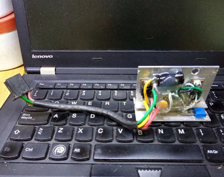
In the video below, an LED was added in the circuit to give a visual indication that the regulator is operating properly. It’s certainly a welcome build for anyone who has ever dealt with rectifier- or diode-style regulators on older bikes before. Vehicle alternators are interesting beasts in their own right, too, and they can be used for much more than running your motorcycle’s electrical system.


Nice project but motorcycle voltage regulators are extremely reliable, probably more reliable than anything I could design. Most are shunt regulators designed to turn on and clamp the alternator to a set voltage range, the string of diodes you mentioned. Motorcycle regulators are designed this way because they are reliableble, low cost and light weight.
Cheap chinese regulators are extremely unreliable. There are constructed using inefficient thyristor circuits prone to overheat and fail after short time, particularly with light loads (worst case scenario for a shunt regulator).
Honda regulators are famously bad. I’ve had to replace them on almost every bike I’ve had. Companies like Electrex make a living out of building higher quality replacements.
I’m never sure whether it’s the regulator or rectifier side that goes, as they’re combined and potted.
I agree with the idea that they should be reliable, but they absolutely are not reliable. On both my Yamaha and my Suzuki they have been replaced within 60.000km.
To continue…
Even though this is a nice project this article is wrong in several ways. For starters, neither a car or motorcycle alternator delivers significant charge current at idle. And it’s current, not voltage. The voltage you measure reflects the charge state of the battery and the regulator assuming the alternator’s current output is high enough to start shunting current across the regulator, and not the alternator itself. And a replacement voltage regulator can’t increase that alternator’s current output at idle in a car or motorcycle. It’s a matter of design and physics. An alternator’s maximum current output isn’t limited by it’s regulator therefore no regulator can increase it’s output current.
At full on, an alternator’s output follows a curve that’s driven by engine RPM. In the case of a car that can afford the space and weight of an oversize alternator and regulator, that output is switched on and off based on the battery’s voltage. And in many cases it’s full on for the first few minutes after you start the car, at least until the energy you pulled from the battery to start the car is returned to the battery. From then on, the alternator is switched on and off by the regulator based on need.
But a motorcycle is constrained by both space and weight. Plus the battery, starter and electrical loads are much smaller, requiring less ‘alternator’ to recharge the battery and to keep up with the electrical loads while you are riding. Because of the space and weight constraints, the alternator in a typical motorcycle is much smaller that a car and by design it’s always 100% on. Then the manufacturer uses a shunt regulator to spill off excess current. The system actually works very well, but only because the alternator’s output and total loads on a motorcycle are miniscule compared to some cars.
And Fernando, you are correct. Cheap aftermarket replacement regulators are extremely unreliable. That’s because aftermarket replacement ‘anything’ electronics usually aren’t driven by the same design standards as OEM or OEM replacements that are manufactured to the same standards as OEM products. And this includes cheap aftermarket replacement regulators manufactured in China. But China isn’t the only country in the world producing junk. We in the USA build our share.
There is another cause for your alternator not keeping up with your battery charge and often the charging system is blamed when the charging system is not at fault. Not operating your vehicle more than a few miles after starting does not give your alternator enough time to replace the energy used to start your car or motorcycle. Do this for a week or sometimes a little longer and you end up with a seriously depleted battery. So, if you are a rider or driver who only takes short trips it’s smart to go for a longer ride at least once a week. Or if fuel costs are a real constraint, you need to invest in a plug in battery tender to replace the energy in your battery that you aren’t giving your alternator time to replace.
>From then on, the alternator is switched on and off by the regulator based on need.
Nope. Common car alternators simply keep the output at 14.4 – 14.7 Volts by adjusting the rotor magnetization current. It feeds some of the output current back into the alternator to regulate the voltage.
Motorcycle alternators are more often a simpler magneto type, which means you get variable voltage pulsing DC from the rectifier and the voltage regulator cuts the peaks by shunting them to the ground. It’s not “always 100% on” – it does not “spill off excess current”.
Don’t correct other people on matters you yourself have misunderstood.
You are partly right and partly wrong.
The 14.4 – 14.7 voltage on a fully charged battery is maintained by the battery’s state of charge. Your battery acts like a huge active capacitor, smoothing out the system’s voltage as your alternator switches current on and off. And the alternator does switch on and off, it does so to maintain that voltage set by the regulator.
As far as ‘continuous output’ is concerned, automotive alternators are three phase and the diode bridge converts this output into 6 pulses a second. And by initially being three sine waves 120 degrees out of phase of each other, the 6 pulses are only 60 degrees out of phase and there’s plenty of overlap between the pulses. So what you have if the battery wasn’t there to act as a huge capacitor to smooth out those pulses, is a pretty steady DC voltage with a huge ripple on top. This steady voltage is why some engines will run with the battery disconnected and that varying RPM dependent light loaded voltage and ripple are why some won’t.
If you have an O-Scope, you can actually see the slight change in your battery voltage as the alternator switches on and off, and you can see the remaining ripple on top of the voltage when the alternator is on.
Fully charged and ‘stabilized’ battery is 12.6 v, 2.1 v per cell. I’ve seen 12.75 from a freshly wetted battery, probably a surface charge
14 + v = some form of charger\alt\gen
My last three bikes had perminant magnet rotors so no spinning electromagnet.
Neodymium and other super magnets have made permanent magner alternators possible. These alternators are smaller, lighter and more reliable than field coil alternators, but they are still alternators as they produce AC current that has to be rectified to DC.
See the second page:
https://www.scubaengineer.com/documents/lead_acid_battery_charging_graphs.pdf
If you allow the charge to continue freely with no limits on the input voltage, just on the input current, it could eventually rise up over 16 Volts. The reason why the battery voltage is higher during charge is called “overpotential” and it’s caused both by the resistance of the battery (which is quite low) and the extra voltage potential you need to run the chemical reactions. In other words, you need a bit extra voltage to get the ions to actually move back from the discharged state. Too much overpotential though, and the electrolyte starts to split into oxygen and hydrogen, and the battery “boils” dry.
See also:
https://en.wikipedia.org/wiki/Overpotential
The overpotential required to charge a lead-acid battery is also the reason why it is not very efficient as an energy storage medium. You lose about 10% of the energy as heat. When the battery is full, there’s still about 60 Watts of power going in just by the floating charge, which keeps the battery warm in the winter, but can cause electrolyte loss in the summer.
>The 14.4 – 14.7 voltage on a fully charged battery is maintained by the battery’s state of charge.
Nope. 14.4 – 14.7 V is the float charge voltage kept by the regulator, not the battery. If the alternator just kept pushing current into the battery with the idea that the battery keeps the voltage down, you’d boil off the electrolyte.
Here’s a simplified version of a typical alternator:
https://www.classiczcars.com/uploads/monthly_01_2011/post-2169-14150813418134.jpg
The darlington pair Tr1,Tr2 draw current through the field coil (rotor), while transistor Tr3 shunts the base current of Tr2 towards negative when the battery reaches a certain voltage set by the zener diode ZD and the bunch or resistors R3,R4,R5 and what appears to be a temperature dependent resistor.
> is a pretty steady DC voltage with a huge ripple on top
Not that huge. If it was pure sine, it would have about 10% ripple on top.
>you can actually see the slight change in your battery voltage as the alternator switches on and off
Maybe, but that’s not a standard feature, and it’s got nothing to do with how the regulator works.
Plus, with older engines that have simpler oxygen sensors, the ECU “hunts” for the correct A/F ratio constantly and that makes the engine RPM go periodically up and down during idle. This also happens to be the point where the alternator efficiency is changing sharply, so it makes the charging current go up and down and that reflects in the voltage.
See:
http://3.bp.blogspot.com/-gUgVDevkPFY/VVug9P8CKnI/AAAAAAAAM8g/7LHWRa96g0I/s1600/Alternator%2BEfficency%2Bvs%2BRPMs.png
“neither a car or motorcycle alternator delivers significant charge current at idle. ”
I don’t know what car you have but I promise you that my
RAV4 DOES indeed produce current enough at idle to not
only put some charge into the battery but also to power
*some* accs.
Now with the headlights on and heater fan at max—No..
not enough to charge. But just sitting at idle, Yes– it WILL charge.
By ‘significant charge’ I’m saying that your alternator’s output is extremely low when compared to its full output, like less than 5% of it’s full output.
Not generally true.
Most alternators have low efficiency at low RPM because they have to spend a significant amount of the current back into the field coil to keep the voltage up despite the low speed, but a 100 Amp alternator will still put out at least 50 Amps with the engine idling.
Tuned (smallframe) vespas like to kill their Regulator due to much higher rpm. My solution Was to use 2 in Parallel, as i also needed Light on my daily driver. No charging circuit at All, but after the Regulator is Fried, next are the bulbs
That’s true, your bulbs become the voltage regulator. And increase the voltage by only 20% (from 14.5V to 17.2V), causes your bulb wattage dissipated to increase by 44% Increase your voltage by another 10% to 30% (18.85V) and now your bulb wattage has increased by 69%
That’s 44% or 69% above the wattage your bulb filaments are designed to run at and those little filaments don’t like that!
While definitely more finicky and fragile, I wonder if something like a robust Sepic MPPT voltage regulator would be feasible, to get as much useful power out of the generator.
A automotive regulator isn’t designed to maximize your alternators output. It’s designed to limit its output. Alternators are sized to support your battery in stop and go city driving, in hundreds of miles of highway driving, with a low charged battery to a fully charged battery. To do this all the time, your alternator has to be over sized for the job most of the time.
A MPPT type regulator is designed to do the exact opposite. It’s design to maximize your power source all the time.
> Alternators are sized to support your battery in stop and go city driving
Actually, mainly for the lights, fans, the ignition system…
One starting cycle pulls roughly 200 Amps, but it lasts for just 1-3 seconds, so it only actually consumes some few hundred milliamp-hours of capacity. Less than 1% of the total charge. It takes just minutes to get the battery back up to starting condition.
It’s not the stopping and going that consumes your battery but standing on the parking lot and self-discharging. In city driving the duty cycle is so low that the car just sits 99% of the time idling the electronics.
I tried an simulated a sepic converter but on the conditions imposed by the motorcycle sistem, with the current technology of semiconductors, a sepic converter results in a bulky, costly and inefficient design. The actual circuit get as much useful power possible, I simulated a conventional regulator together with my version to verify it.
thanks for posting this. there was a time when i would have built this, and i may have to again. I think there is a need for an open source through hole community design for single and three phase motorbike/atv regulators as well as cdi. that way everyone can work over the flaws in order to make the design more robust.
Initially was thinking to sold this design to a local business (Pietcard) who make some good quality electrical parts for motorcycles. But think it twice an post it, because of the reasons you say.
I’m not qualified to determine if this is more or less robust than the more traditional approach, but I like the author’s process and reasoning – dissipate as little power in the rectifier and shunting elements as possible.
Fernando does this by building a full bridge rectifier out of Schottky diodes and n-channel mosfets. But the really clever bit is using these same mosfets to shunt excess current.
I do have a few questions though:
How does shunting the extra current impact the shaft power required by the alternator?
How do the mosfets fair against the voltage spikes at the input that I imagine would happen when current suddenly changes from near short circuit to powering the load?
I also looked at his design, I think he did a great job. He’s shunting extra current just like the OEM regulation does. So there should be no load difference on the alternator. The one difference in his design is the Schottky diodes in the full wave bridge. The voltage drop across those diodes should be less than OEM.
I only question two things. 1. Does the lower voltage drop make enough difference? And 2. Knowing what I know about design for manufacturing, how reliable is his regulator compared to a quality manufactured voltage product? I guess he will find out, and I hope he shares his results with us a year from now.
Steven, first you are missing the synchronous rectification use of the same MOSFETs, maybe my English isn’t sufficient good to transmit it on the original article.
In response of your questions:
“How does shunting the extra current impact the shaft power required by the alternator?”
A good short circuit generate a bigger current for the same speed of the engine, a bigger current that will be disponible for the load when MOSFETs switch off. In traditional circuit less current developed on short circuit, the short circuit current over parasitic inductance is te voltage generated on stator minus the short circuit voltage on the regulator, over the parasitic inductance of stator.
On traditional regulators this shot circuit voltage is several volts, on the mosfet version almost zero.
“How do the mosfets fair against the voltage spikes at the input that I imagine would happen when current suddenly changes from near short circuit to powering the load?”
When MOSFETs open, the stator voltage is clamped by the Schottky diodes to battery voltage, protecting all the circuit from the destructive voltage otherwise developed.
Excuse me, y misinterpreted one of the questions, from the point of view of the engine, a good short circuit generates a 100% reactive power on the system, reactive power go back to the source, Theoricaly taking no energy from the engine. On a real stator with enamel copper and iron laminated
always be a constant power drag from the engine an the benefit of a good short circuit will be much less, I estimate a 20-30% Les drag at much.
Fernando, thanks for your thoughtful responses – that makes a whole lot of sense.
Yes, the problem is however that the short circuit is never good with several ohms of real resistance along the wires, which doesn’t return the energy back.
I measured DC resistance below 0.5 ohms, but iron core loss will be greater at operating frequencies because laminations are thick (low quality manufacturing).
I did something somewhat similar (and hackaday featured it) because my voltage regulator (admittedly slightly different purpose) was a bimetallic strip with a resistive heater wound around it, rapidly snapping silver contacts on and off to maintain a 12.5v output. A modern switching regulator was a nice improvement, although to be fair the original voltage regulator did power the car’s instrument panel for 45 years before failing. I’m not sure that the modern switching regulator will last another 45 years.
For a long term and sporadic use your solution is more robust and a good engineering choice. My regulator have
some electrolític capacitors with a guaranteed service life of approximately 2000 hours, on log term it will fail. Electrolítics are known to fail if exposed to large periods of time without use.
I am building a schottky rectifier for my 1977 Yamaha XS500. The problem is as you mentioned, not enough voltage generated at low rpm to keep the charge up. I will try the schottky iea as the reduced voltage drop should help the low speed charking slightly, but another concern is the voltage to the field winding being too low.