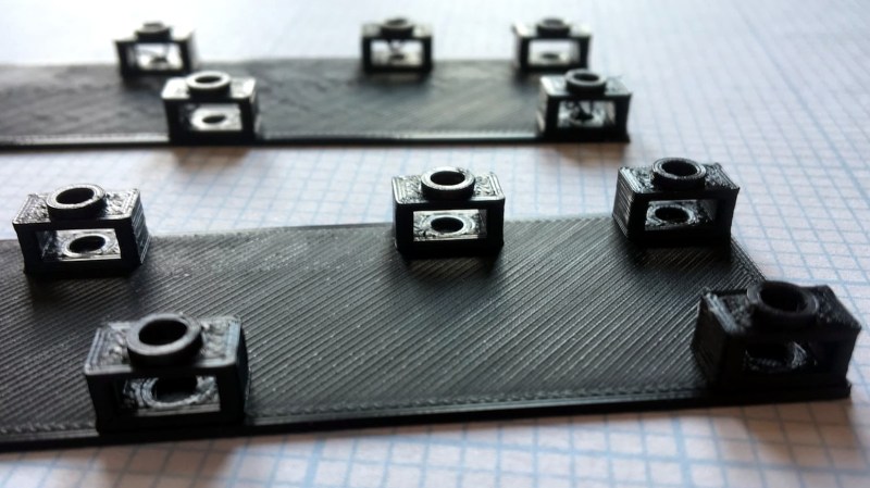
[Tommy] shares a simple 3D printing design tip that will be self-evident to some, but a bit of a revelation to others: the concept of a sacrificial bridge to avoid awkward support structures. In the picture shown, the black 3D print has small bridges and each bridge has a hole. The purpose of these bits is to hold a hex nut captive in the area under the bridge; a bolt goes in through the round hole in the top.
Readers familiar with 3D printing will see right away that printing the bridges might be a problem. When a printer gets to the first layer of the bridge, it will be trying to lay filament in empty space. By itself this is not usually a problem as long as a bridge is short, flat, and featureless. Unfortunately this bridge has a hole in it, and that hole means the printer will be trying to draw circles in mid-air, rather than simply stretching filament point-to-point across a gap. One solution would be to add a small amount of support structure, but that just moves the problem. Removing small supports from enclosed spaces can be a real hassle.
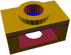 To solve this [Tommy] added what he calls a “sacrificial bridge”, shown as blue in the CAD image. He essentially gives the hole a flat bottom, so that the printer first lays down a thin but solid bridge as a foundation. Then, the portion with the round hole is printed on top of that. With this small design change, the print becomes much more reliable with no support structure required.
There is a bit of post-work involved since each hole needs to be drilled out to punch through the thin sacrificial bridge underneath, but it definitely beats digging out little bits of support structure instead.


good idea! I add another one: when capturing a nut, capture a square nut. DIN 577, a german standard, defines square nuts with the same width as the equivalent ISO hex nut.
i used square nuts in my pi tablet case. they are mostly used hardpoints for addons. i friction fitted them in slots in the edges of the case. was going to friction stir weld them into place but they had a good friction fit and would stay put without much encouragement. the only overhangs in this case were the tops of the screw holes. square nuts are great for this kind of thing.
I made this several times. Like in this barometer project:
https://hackaday.io/project/27500-3d-printed-cute-barometer
I left the lower half of the flange unperforated so that it requires no support material to print and after printing I made a hole in it using the soldering iron.
https://cdn.hackaday.io/images/5198701506606092022.jpg
Huh, that actually makes a lot of sense. Cool hack!
I believe I first learned this trick from Nophead’s blog posts about the design of the Mendel90. Since then I’ve used it many times. Usually I just trim out the bridge layer with a craft knife, but occasionally a drill is easier.
This trick is pretty ancient, but Nophead has an even better technique where you don’t even need any post print cleanup: http://hydraraptor.blogspot.co.nz/2014/03/buried-nuts-and-hanging-holes.html?m=1
I’ve been doing this for a few years. Can’t remember if I saw it somewhere or just came up with it.
The once popular Greg’s Wade’s extruder uses this trick on the extruder body for the bearing and the motor mount holes.
A related hack .. if. you have an overhang that is too small to persuade the slicer to generate support, but edge for the overhang needs to be precise, make a super-thin (like 0.1 mm thick) feature that juts out far enough to persuade the slicer to generate support. This generally results in a well formed edge for the overhang, and the sacrificial feature is easy to grind or sand off.
nophead did this a lot on the mendel90 parts
Does the software used to define 3D prints know to stretch filament across gaps, or does the user have to somehow define the direction for the filament in those areas?
Most slicers autodetect bridges nowadays. But if there is a more complex structure, like multiple bridges in a grid pattern on the same layer, it varies how smartly the slicer does it.
Designing the structure and doing the steps needed for capturing a nut can be quite a lot of work. I usually just put in a hole and then use soldering iron to melt in a threaded insert.
That seems to be a very good solution. At least if you can purchase threaded inserts as easy as nuts. But I just thought about melting hex nuts in fitting holes with the iron. This should be of similar strength than captive nuts.
That makes a lot of sense. Thanks for the tip!
I would simply put a single wall cylinder between the holes.
Matching the hole ID.
This supports the bridge and keeps the bottom of the hole nice and crisp.
You simply cut it away after printing.
it’s workable, but as the article says, it can be relatively difficult to remove that support, depending. the article’s recommended layer is always easy to remove with a drill bit.
also, if you’ve got a bowden extruder, then a thin tube like that has its own potential problems *sigh*
Just turn it 90° and print it on its side. It will be stronger if the force is up and down (in the picture) and no supports needed.
Wait. I thought it was just the individual piece. Sorry for the dumb comment.
i independently invented this. *pats own back*
did i tell you all how i invented micro-blogging (twitter) in 2004?
but really, for nut traps i usually make walls instead of ceilings…
Don’t mess around, just make the damn things solid and press a red hot nut in from the side :-P
Just leave out the nut, print a solid block with a center hole and then tap it yourself with a 3€ tool.
Best additional investment to my printer was a set of tap drills and a wrench.
Beware that usually those taps are made for through-hole – if you need blind holes, there are special drills for that as well where the thread climb is way sharper.
… or forget tapping entiirely for M3 to M6 and just make it a tight fit. Cut (or just deform) threads with the screw.
Works best in ABS or PET-G or similar — the plastic needs a little give.
Yup, that’s my preference. Screw right into the plastic.
Yet another elegant solution is to just capture the nuts in the print: you leave out a nut-shaped space in the model (with just enough extra space on the sides to be able to insert the nut without having to press it in) and add a stop command in the print at that layer height. When the printer stops, you manually insert the nuts and then tell the printer to continue and print over the nuts. That way, you don’t have the bridge problem in the first place and the nuts end up totally encased except for the hole on top.