[Adrian] has a lot of retrocomputers, so he uses an RGB to HDMI converter to drive modern monitors. In particular, he has a box that uses a programmable logic chip to read various RGB signals and ships them to a Raspberry Pi Zero to drive the HDMI output. Sounds great until, of course, something goes wrong.
A converter that had worked stopped working due to a bad board with the programmable logic chip on it. Unlike the retrocomputers, this board has little tiny surface mount components. A little analysis suggested that some of the chip pins were not accepting inputs.
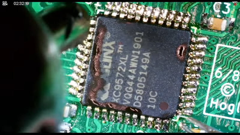
The Xilinx device has 5V-tolerant inputs and [Adrian] thinks that 5V inputs may have fried the inputs which can happen if there is 5V on the pin and the device isn’t powered up. The plan was to remove the bad chip and replace it with a new one.
As SMD parts go, the Xilinx chip isn’t particularly tiny, but if you are more accustomed to working on 1980s computers, it can be a bit of a challenge. [Adrian] wisely used a lot of flux and hot air to remove the part. We might have covered the adjacent components with Kapton tape to avoid taking off more than we wanted.
Another idea is that if you are sure the part is bad, it is sometimes easier to cut all the leads off, dispose of the chip, and then remove each pin one by one. He got it, though. We might have cleaned the pads before resoldering them, but [Adrian] elected to just add fresh solder and that did work but the excess solder made it harder to place the new chip.
It took a few tries, but persistence is the key. Luckily, the board was high quality and took a lot of heat as well as the part. If you are timid about doing SMD work, you might find [Adrian’s] journey inspirational. It does help that he has a great microscope. In the end, it worked despite some problems with the video capture causing some confusion on colors.
This isn’t really a tutorial on SMD rework, but more of a first-time diary. If you want something more instructional, check out [Bil Herd’s] post. Or, spend an hour with [Moto Geek].


ChipQuik is your friend
Just be make sure to get it *all* off the board before you put down the new part
Even just adding leaded solder can make rework easier.
they can have my 60/40 when they pry it out of my cold dead hands.
63/37 “Eutectic”, but yeah – ’till death do us part!
The existing tin on the pads will dilute 60/40 towards the eutectic ratio, if you start at 63/37 the plasticity range is only going to increase on lead-free examples
Or just use any other that behaves the same. Like Rose’s metal, Wood’s metal and so on. Costs a fraction, does exactly the same.
Wood’s metal contains Cadmium. It is NOT a safe substitute for Indium-bearing solder.
The question is: Do you really want to eat the solder?
Enjoy the fumes.
Metals don’t vaporize at soldering temperatures. The fumes are entirely from the flux.
Now, *handling* the solder puts metal residue on your fingers, which you can easily transfer to your mouth. I have no interest in doing that with cadmium.
This seems to be an ordinary 44 pin QFP. A hot air gun and some good solder (Sn/Pb) shall do the trick.
A little bit of low melt solder would’ve made it a lot easier, then desoldering wick to remove the low meld solder, clean up with alcohol and swabs and apply no clean flux and some fresh 40/60 solder. Solder the new chip. Remove excess solder with hoof/well type soldering iron tip (the one for drag soldering) and/or desoldering wick. Check with a needle nose tweezers if all pins are soldered.
Cleanup with isopropyl alcohol and a brush and some paper towels, and finish it off with some swabs.
I wonder whether anyone here has actually watched the video at all before commenting. He has hot air – which should make short work of that chip. Except:
– he uses liquid flux which flashes off almost instantly when heated – no good, should use gel flux instead.
– he uses a tiny diameter nozzle to desolder a TQFP144 chip – which can’t heat the package enough to actually make the solder to melt.
That’s why he was struggling with it.
No, I did not watch the video. But from the images: it is a 44pin chip, not 144 pin. And I would use just an ordinary heat gun. If necessary some Kapton ttape or just Aluminium Foil to shield the rest.
It’s only a QFP44. Replacing it isn’t rocket science.
1. Remove using a hot air gun with a nozzle made for the QFP44 – it has four jets arranged in a square to direct the hot air at the pins instead of all around the PCB.
2. Put down the flux. Put it far away. Seriously. If you think you need flux, you probably don’t. You are REMOVING a part here, not installing it. Flux is to make the solder flow and bond better while installing a part.
3. Heat the pins with the hot air and the proper nozzle until the solder melts.
4. Pluck the part off the board with a pair of tweezers. Grab one of the pins through the gap between the four parts of the nozzle.
5. Clean off the pads with solder wick. You want them all flat and shiny.
6. Clean off any flux that was left behind.
7. Put a small blob of solder on one pad, at one corner of the IC.
8. Solder the IC down to that one pad, making sure to align it.
9. Solder down a second pin, diagonally opposite the first pin.
10. Check the alignment. Heat one or the other of the soldered pins and rotate or shift the IC as needed to fix the alignment.
11. When the chip is properly aligned, solder the other pins down. Drag solder and check for shorts or solder each pin one at a time then check for skipped pins.
12. Again, keep that freaking flux out of the way. Use good 0.5mm solder with a flux core. If you have to flood everything in flux, you need to practice soldering.
13. Clean up the excess flux using alcohol. Even if you don’t add extra flux (and you shouldn’t need to,) there will still be excess flux from the solder.
>12. Again, keep that freaking flux out of the way. Use good 0.5mm solder with a flux core. If you have to flood everything in flux, you need to practice soldering.
That’s actually completely wrong. If you are using only the flux in the solder wire, you have guaranteed cold joints the moment you have to touch the joint up because by then the original flux has evaporated/burned off and is not effective anymore. That’s the technique that worked with through hole parts and point to point wiring, where one was constantly adding fresh solder (and thus flux) but it does not produce good results with SMD repair!
There is nothing wrong with “flooding” anything with flux – I want to see you how you would even manage without “flooding” with some smaller components. Excess flux is never a problem (as long as one cleans it off afterwards), not having enough is a guaranteed issue that could be difficult to spot and track down.
Good extra flux is essential to both desoldering the old component (it helps the old oxidized solder to flow and also spreads the heat) and also to soldering a new component on. You won’t see anyone skilled in SMD soldering working with only the flux inside the core of the solder wire, especially when working with hot air. And no, I am not talking about Louis Rossmann who also constantly gets complaints about “using too much flux” like this.
That’s the way I used to remove and replace QFP44 microprocessors.
Care to gues how many of them came back for repair? Zero.
I used to do this for a living. All day, every day. Hot air to remove, soldering iron to reinstall.
My coworker tried resoldering with hot air and destroyed several PCBs that cost several hundred bucks a pop.
I solder 0402 and 0201 passives by hand with a soldering iron and regular solder – no additional flux.
I solder 16 pin SSOP parts by hand with a soldering iron and solder – and no additional flux.
Yeah, I count myself as skilled at soldering SMD parts. I don’t use extra flux.
I’ve been using SMDs since the mid 1990s. I prefer SMD to through hole.
Congratulations. You win. But mere mortals need to use flux.
Similar, but I would raise the white flag at 0201. And if necessary I use some extra flux for soldering. If a desoldering situation is difficult, it is mostly leadfree, so adding some good SnPb solder helps.
And here I thought it was going to be about the connectors. USB is designed (mostly) to have the male end be the wear part, HDMI appears to have the socket be more fragile. I’ve lost a couple components (A DVR in particular) to a badly-handled cable, which just shouldn’t happen.
Kudos to [Adrian] for showing this video. I hope he will find this article as there is some good advice here (in the article and the comments). I just would add to pratice on some garbage-boards before trying to do an actual repair. Shouldn’t be to difficult to find some broken, worthless electronics with plenty of SMD on the PCB… And again +1 for Kapton tape! In my experience the stuff from Aliexpress works quite well (and is probably much cheaper than the original stuff).
If your took kit is limited but you have a loose razor blade or a sharp scalpel at hand, a little 44-pin QFP like this can be removed fairly easily in minutes. With a sharp blade the pins cut through like butter up against the body of the device, especially if you slice just one at a time.
Unless you’re hamfisted you shouldn’t find it hard to avoid touching the board with the blade or exerting enough mechanical leverage against a cut pin to cause a pad to lift. Just rest the suitably angled blade on top of the pin to be cut, butted up against the device package and then apply a little pressure to the top of the blade with your thumb. The cut pin can then be flicked off the board with your soldering iron.
tool, not took.
Why would you even think about doing this if you have a hot air gun? And if you want to be extra safe, drag solder on all sides with leaded solder first, then remove the excess simply by dragging the clean soldering iron tip on the pins, then use hot air to remove it. Cutting the pins is unnecessary stress on the pads and yoh don’t know how structurally sound they are.
FFS the very first words of my post were: “If your tool kit is limited…”
your words were “If your took kit”
I used to play with these xc9572s indeed they are retro in themselves. I used the plcc44 capsule and it has a 0.1″ space socket that goes with it. Just flip it out with a screwdriver and in with another one. The Big pita is actually the xilinx sw.