A few weeks ago we posted a build of an avid motorcycle enthusiast named [fvfilippetti] who created a voltage regulator essentially from the ground up. While this was a popular build, the regulator only works for a small subset of motorcycles. This had a large number of readers clamoring for a more common three-phase regulator as well. Normally we wouldn’t expect someone to drop everything they’re doing and start working on a brand new project based on the comments here, but that’s exactly what he’s done.
It’s important to note that the solutions he has developed are currently only in the simulation phase, but they show promise in SPICE models. There are actually two schematics available for those who would like to continue his open-source project. Compared to shunt-type regulators, these have some advantages. Besides being open-source, they do not load the engine when the battery is fully charged, which improves efficiency. The only downside is that they have have added complexity as they can’t open this circuit except under specific situations, which requires a specific type of switch.
All in all, this is an excellent step on the way to a true prototype and eventual replacement of the often lackluster regulators found on motorcycles from Aprilia to Zero. We hope to see it further developed for all of the motorcycle riders out there who have been sidelined by this seemingly simple part. And if you missed it the first time around, here is the working regulator for his Bajaj NS200.


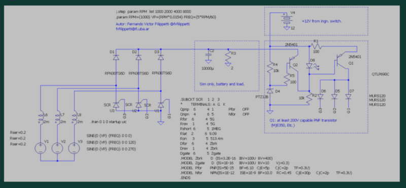
Just a minor note: In the simulation image at the top of the article, the 3 phases are 0°, 120° and 270°. I think they intended 240° although it won’t make any appreciable difference to the simulation.
I think that accounts for the difference in amplitudes for the three diode currents, and probably for some of the ripple showing in the output voltage.
you are right, i made a typo error but as you say there are no appreciable differences on simulation.
Few notes: parallel diodes and SCRs need individual resistors because of the negative temperature coefficient of the junction. The one that gets hot first will draw more of the current, so he might end up with an unstable rectifier.
The voltage set point needs to adjust higher to about 14.4V to account for the charging overpotential. It should also ideally adjust by the ambient temperature, but you probably won’t drive your motorcycle in the winter anyways.
Hi,
where do you see SCR or diodes connected in parallel? Recommended floating voltage for lead acid is 13.8 V. 14.4 V should only be used to terminate a charging process. The situation in the motorcycle is most of the time floating and not charging.
From Q1 down through D5,D6,D7 to U1,U2,U3. The current is limited by R1 and branches to three parallel paths. This wouldn’t be an issue if only one of the SCRs was in forward conducting mode at a time, but since this is a three phase alternator, two will see forward bias at the same time and share the current from Q1. The branch with the lower threshold voltage will take all the current – in the simulation they’re all perfectly identical so you don’t see any problems.
> The situation in the motorcycle is most of the time floating and not charging.
A lead-acid battery needs some overpotential to actually charge. Keeping it at 13.8 Volts just prevents it from discharging when full.
The reason to go above 14.4V is to balance the cells. If you only ever charge up to 13.8 V the cell voltages will begin to drift apart and some will over-charge while others will never fill up. Automotive batteries are typically charged at up to 14.7V for this reason – not at floating voltage while the engine is running. The other reason is that it charges up faster (takes more current) which is needed to replace what was lost to self-discharge while the vehicle was parked.
You’re right, the first one to activate is the most negative (a design choice), but once it activates the most negative becomes another SCR and activates that too.
My mistake. I read the diagram and saw the voltage referenced was the battery terminal, but it is instead the alternator output when the SCR is not yet open. Once it is open, the gate voltage lifts up towards the battery negative terminal and allows the next gate to open.
I’m was thinking DC circuits where the cathode is commonly connected to the same voltage reference, so connecting two or more SCR gates in parallel can result in just one of them actually turning on.
“lackluster regulators found on motorcycles from Aprilia to Zero”
I’m not sure you’ll need one on a Zero.
The 3 phase design would be more useful if it was also compatible with single phase stators, because that would require less parts to be kept on the shelf. Can anyone verify if that is the case here, even though it would be obviously more expensive to build than the single phase regulator.
it’s fully compatible, yo can omit U3 D1 and D6 to make a mono-phase version.
My use case was to leave the parts in circuit but not wired to the motorbike, however it sounds like that will work fine. Thank you for designing this.
It doesn’t look like there’s anything 3-phase-specific in the design; a single driver feeds all three of the SCRs, so this should work just as well for single-phase alternators. What it WON’T work for is a DC generator, since the SCR won’t ever turn off.
It will turn off when reverse biased.
Will the circuit be able to handle bikes that have either no battery, or a smoothing capacitor instead of a battery?
Will work, but In absence of battery or capacitor the rectified voltage will have very high voltage peaks. I recommend at least 4700uf capacitor. For a motorcycle with no battery and no capacitor shunt regulator is best, but I do not recommend this setup anyway.
I think it’s time these regulators on car and bikes went MPPT. They have to accommodate such a wide range of RPM that the system is inevitably poorly matched. Also, once you go to the trouble and complexity of an MPPT converter, you may as well go synchronous. With the low losses, a heatsinkless design could be possible, and even better, a potted design. Tough, waterproof, automated eledctrical assembly. Only potting required.
New motorcycles have auto stop feature and implement synchronous rectification with the same starter-motor/alternator composed of a huge 3 phase stepper motor. But they don’t implement MPPT because will end on a destroyed overcharged battery. MPPT is for optimize low power sources and transfer power to a electrical net or a huge battery bank. If you implement it on a power alternator and transfer power to comparatively small battery will fail almost for sure. Other problem with MPPT is the time required to reach equilibrium on MPP, on motorcycle conditions change very fast in seconds rendering mptt algorithms useless.
That first part is interesting. Last week I was thinking about if I could rewire the stator as a BLDC motor and use it as a starter.
But you’re not trying to get maximum power out of the alternator – you’re trying to get only as much as you need.
I agree with @Murray, the technology used in all of the ATV regulators I’ve torn down has been very primitive compared to most power supplies and chargers that are on the market now. MPPT (when the alternator / generator is running at maximum load), better charge controlling, and better load regulation should be easily achievable using chip solutions that already exist.
Completely different problem. MPPTs were developed specifically for photovoltaic panels, because these deliver voltage and current in a tricky way that requires controlling the current you draw from them. If you try to draw too much, they deliver LESS power. Not the case for generators or alternators.
From my experience with a 1982 Goldwing a good alternative regulator would be a 2004+ Yahama R1 regulator. It uses MOSFETs and supposed to be the best regulator you can get for a typical motorcycle.