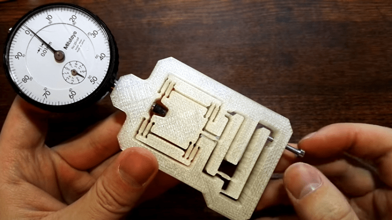
Here’s an older but fantastic video that is as edifying as it is short. [Topias Korpi] demonstrates a 3D printed flexure with a dial indicator on one end, and an M3 screw on the other. As the screw is turned, the dial indicator moves steadily with roughly a 15:1 reduction between the movement of the screw and the indicator. Stable deflections of 0.01 mm are easily dialed in, and it’s neat seeing it work while the flexure itself shows no perceptible movement. A demonstration is embedded below the page break and is less than a minute long, so give it a watch and maybe get some ideas.
Flexures are fantastic designs capable of a wide variety of physical functions, and just as [Topias]’s demonstration shows, they can be a natural complement to 3D printing. In fact, flexures are an important part of the design and function of JWST’s mirror actuators, which are responsible for making astonishingly small adjustments to each of the space telescope’s 18 mirror sections.


Small tip:
When you design a flexture, then don’t “drill” round holes around the hinge points, because these are huge stress risers and and promote premature failure through fatgue. Instead, use a thin section with a bit of length to spread the bending force in the hinges.
Isn’t the stress supposed to be concentrated in reasonably small area? If you spread it too much, your effective pivot point might move around that area, which might be bad for precision and repeatability over time.
Yes, having the wall thickness drastically reduce where the ends are isn’t ideal. I guess the designer wanted a large radius to get rid of stress fractures, but ended up overdoing it.
Though, I see little reason for why they couldn’t just space the segments out more to actually have room for the desired radius.
I ran a quick FEA on the part and the stresses are super low in the flexures. At 2mm input displacement, the stresses are about 0.02% of PETG yield. The maximum stress is actually in the long straight flexures on the first input part. The flexures on the final output move so little, there is less stress there.
FEA results: https://www.thingiverse.com/make:1038046
FLEXURE, not flexture.
Whoops! What a goof, thanks for that!
Very cool. Cool applications of mechanical engineering never cease to amaze me
Interesting, wonder if you could “tune” a crystal like that.
It’s just a two levers right?
The implication is that the screw position is linear and repeatable. Not sure I would agree. Over time, temp, humidity, etc the dial will move despite the screw staying still.
With a waterjet you can cut them from Cermet.
This appears to be a 3-d printed version of the item in Dan Gelbart’s flexure lecture. It’s used for nanometer-scale positioning of optical components.
https (colon-slash-slash) www (dot) youtube (dot) com/watch?v=PaypcVFPs48
The entire series is something like 15 lectures, but pertty interesting for makers.
Would also be useful of course for positioning the needle on atomic scale gramophone records.
Go perfect with the worlds smallest violin.
Can you please explain how the 15:1 ratio is determined, more broadly, g
how would one generaly derermine the ratio on any given linear flexure? thanks for the help
I ran an a finite element analysis of the mechanism in a comment above and found its ratio to be closer to 10:1. To calculate it by hand, look at the length ratios on each beam. The input beam is about 5:1 — the total length from the left pivot to the input shaft is about 5x as long as the length from the left pivot to the output shaft. The second beam is about 2:1 with the same reasoning. The big square thing at the top just moves 1:1 withe the output from the second beam. Multiply them all together and you get 5x2x1=10.
thank you, also, what program did you use to generate the FEA?
ANSYS
Cool. I am thinking to try this with a 508 TPI screw/ferrule which I have lying around. The plastic I have in mind if the Shapeways Nylon (their cheapest). I also wonder how the final product reacts to humidity changes and what creep is like. Finally, I wonder if I should glue a W carbide plate where the screw tip engages the first lever. I should have no issues tracking sub-micron movement under my microscope (calibrated with a PI stage).