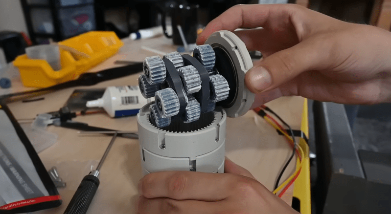
Affordable brushless motors are great for a variety of motion applications, but often require a gearbox to tame their speed. [Michael Rechtin] decided to try his hand at designing a stackable planetary gearbox for a brushless motor that allows him to add or remove stages to change the gear ratio.
The gearbox is designed around a cheap, 5010 size, 360 KV, sensorless motor from Amazon. Each stage consists of a 1:4 planetary gear set that can be connected to another stage, or to an output hub. This means the output speed reduces by a factor of four for each added stage. Thanks to the high-pressure angle, straight-cut teeth, and fairly loose clearances, the gearbox is quite noisy.
To measure torque, [Michael] mounted the motor-gearbox combo to a piece of aluminum extrusion, and added a 100 mm moment arm to apply force to a load cell. The first test actually broke the moment arm, so a reinforced version was designed and printed. The motor was able to exert approximately 9.5 Nm through the gearbox. This number might not be accurate, since sensorless motors like this one can not provide a smooth output force at low speeds. As [Michael] suggests, adding a sensor and encoder would allow for better testing and low speed applications. Check it out in the video after the break.
We’ve featured a number of [Michael]’s projects before, including a bag tracking corn hole board, and a 3D printed linear actuator.


Gear boxes like these really need several hundred hours of testing under load before any useful conclusion about their usefulness can be made. And a lever hitting a load cell is not a good way of testing this. It’s much better to put an axle on it and wrap a cord around it to make a winch for endurance testing.
This also leads to optimisations such as wider gear for the higher torque sections.
But also, because when you start printing gears, a modular gearbox really is not of much use. When you start printing it’s much better to make the model parametric, That way you can for example make a 1:8 first stage with smaller teeth, and a 1:3 reduction stage with larger teeth that can handle higher torque.
Another improvement would be to ditch the ball bearings and bolts, and replace them with hardened ground axles (precision bolts?) and needle bearings. Both such axles and needle bearings (with integrated outer shell) are cheap off the shelf products. (For example HK0306, but they are available in many sizes).
I’am also guessing that using different plastics would improve endurance significantly (for example cheap PLA for the outer ring gears and a tougher plastic for the smaller gears)
Letting it lift and lower a weighed bucket for a few weeks (until it fails?) while monitoring it with a camera does not take much human effort, but would make the video much more intersting. When you start comparing the longevity of different gearbox confirugations it would make it even more useful, but that would also take considerably more effort.
Very good points. My first though was also the same: need some type of endurance test.
What happens with use outdoors in the heat or in cold conditions? Does the material become soft and deform/brittle and fall apart?
PLA is definitely not the best material for this usage, I think Nylon would be much better. PLA tends to wear out easily, since it’s too brittle. Plus it doesn’t withstand more than 60°C without going soft. whereas Nylon is miles better in terms of friction and still easily printable unlike POM or Delrin.
Also, what benefit would needle bearings and ground axles bring here? just curious. I don’t see the problem with regular bearings
Is there a link to a git repository or something? (or is this just a YouTube video?)
The description just under the youtube video has a link to
https://drive.google.com/drive/folders/1HSmXk7esxMBL1d4LxMr3W6cn4hLdanLj?v=G0DcM60lWSw
… which has links to .step and .stl files, but not the real CAD files, which makes making something similar (but different) difficult.
Doesn’t a large amount of noise imply energy being wasted and wear on the gears? (Not that I could construct something of this kind myself, I freely admit.)
Waste of energy yes, but perhaps not so much wearing. The noisiness in these kind of things, I’ve built similar ones before, is mainly from the faster moving earlier stages where there is less force present, whereas the wear tends to happen in the slower high torque later stages.
Wow. Nice work. Learned some stuff there. Well designed. Thank you.
It would actually be easier, and more effective to 3d print a set of CVT cones tied together with a standard automotive belt to test (and operate) this. Less stress on the components, quieter operation and likely better torque coupled to cleaner output. There are several examples on Thingverse and other places. No need to re-invent the wheel.
I don’t think these planetary gears can shift like a slush box.
If you wanted to do it with a belt and pullies it would be simple. That’s not the point.
Not entirely sure what the point is, but it’s not building a useable gear train.
Excellent progress!
Congratulations!